NCC 2022 Volume One - Building Code of Australia Class 2 to 9 buildings
Search the National Construction Code editions
J6
Part J6 Air-conditioning and ventilationThis Part contains Deemed-to-Satisfy Provisions for compliance with Part J1. It sets out the provisions for the efficiency and control of air-conditioning, space heating and ventilation equipment, the efficiency, sealing and insulation requirements for ductwork systems containing fans, and for the efficiency and insulation of pipework and pump systems.
From 1 May 2023 to 30 September 2023 Section J of NCC 2019 Volume One Amendment 1 may apply instead of Section J of NCC 2022 Volume One. From 1 October 2023 Section J of NCC 2022 Volume One applies.
In Tasmania, for a Class 2 building and Class 4 part of a building, Section J is replaced with Section J of BCA 2019 Amendment 1.
To clarify that the requirements of J1P1 to J1P4 will be satisfied if a building complies with Parts J2 to J9.
See comments on J2D1.
The Deemed-to-Satisfy Provisions of this Part do not apply to a Class 8 electricity network substation.
Part J6 generally contains minimum energy efficiency requirements for the major energy consuming components of heating, ventilation and air-conditioning systems (HVAC) used in buildings.
Class 8 electricity network substations are exempted from Part J6. These substations commonly operate mechanical ventilation or air-conditioning 24 hours a day to serve high voltage equipment, so manual override or specific design features for energy efficiency could be hazardous. See definition of “air-conditioning” in Schedule 1.
It should be noted that the NCC cannot regulate operational matters such as the set point for temperature control devices during the occupation of buildings. It can only require that temperature control devices be installed.
Note that Part J6 is about air-conditioning units and systems. So, the applicable floor area is only that of the space served by the air-conditioning unit or system, and does not include non-conditioned corridors, toilets, plant rooms and the like.
| Climate zone | Total air flow rate requiring an economy cycle (L/s) |
|---|---|
| 2 | 9000 |
| 3 | 7500 |
| 4 | 3500 |
| 5 | 3000 |
| 6 | 2000 |
| 7 | 2500 |
| 8 | 4000 |
To set the minimum control requirements for air-conditioning systems and components.
J6D3 is about the control requirements for air-conditioning systems so that the consumption of energy is limited.
J6D3(1)(a) requires controls to deactivate the air-conditioning system when the area is not occupied and is intended to only apply where the building or part of a building served by the air-conditioning system is unoccupied. For example, if an air conditioning system serves a whole building, it is only required to be capable of being deactivated when the whole building is unoccupied. Similarly, if an air-conditioning system only serves a single floor of a building, the system must be capable of being& deactivated when that part of the building is unoccupied. It is likely this clause will require the operational arrangements to be designed on logical building areas and segments.
J6D3(1)(b)(i) outlines that when one space has different thermal characteristics to another space, and both are conditioned by the same air-conditioner, it is necessary to provide separate temperature control devices. A suitable location of the temperature control devices maybe in the ductwork supplying the different spaces or the air volume dampers.
For example, consider the differing thermal characteristics between a south and east facing room due to the differing solar gains received. If the temperature sensor is in the east facing room it may activate a higher level of cooling than the south facing room may require. This may result in the south facing room being cooler than desired. An additional temperature control device will allow separate control of the space, facilitating reduced energy use.
J6D3(1)(b)(ii) requires the temperature control of the air-conditioning system not depend on mixing heated and cooled air streams that have been actively conditioned by the plant. This requirement allows the air-conditioning system to use no more energy than is necessary.
J6D3(1)(b)(iii) contains restrictions on reheating the supply air. These requirements are intended to encourage the grouping of areas with similar loads (heating and cooling demand), rather than sub-cooling all the supply air and reheating excessively to achieve the desired temperature.
J6D3(1)(b)(iii)(A) outlines that where a separate temperature control device is provided to reheat the air, then at the full supply air rate for the space, it must not increase the supply air temperature by more than 7.5 K, as there are more cost effective solutions. The 7.5 K limit on temperature rise allows for some trim heating of cold air supply but within reasonable limits.
J6D3(1)(b)(iii)(B) outlines that the allowable temperature rise can be determined by using an inverse relationship between allowable temperature rise and supply air rate. If, during the reheating, the supply air rate is also reduced then the temperature rise can be proportionally increased above 7.5 K at the same rate that the supply air rate has been reduced. For example, the reheat temperature could be increased to 10 K when the supply air rate is reduced by 25% or increased to 15 K if the supply air rate is reduced by 50%.
J6D3(1)(c) requires outdoor air economy cycles to be provided where they can cost-effectively provide free cooling, however an area needing humidity control is exempt. Outdoor air economy cycles are not required in climate zone 1.
In this clause, the total air flow rate of each air side component means the air flow of each air-conditioner serving a space, not the combination of all the units serving a space because an outdoor air economy cycle is cost effective only in a larger unit.
Outdoor air economy cycles can be cost effective particularly in a building such as a Class 6 restaurant or café with a low occupancy. However, there may be situations where the outdoor air required by Part F6 maybe so great that an outdoor air economy cycle would admit only a small additional amount of outdoor air. The added cost of dampers and controls may not be justified for energy savings returned, so a Performance Solution may be more appropriate in these circumstances.
An exemption is granted to applications that require humidity control. It is considered the additional cost and energy use of humidification or activation of a dehumidification plant offsets any benefit of free cooling from outdoor air economy cycle. These applications may include, but are not limited to, a frozen food section of a supermarket, a laboratory or a paper manufacturer’s factory.
J6D3(1)(d) requires the water flow through major items such as boilers and chillers to be stopped when the item is not needed, usually by an automatic valve. This will reduce the amount of water being circulated and the pump energy needed, as well as thermal loss through the additional components like piping. This requirement is intended to reduce pump energy to its minimum level.
J6D3(1)(e) outlines that a variable speed fan must be used when the supply air quantity is capable of being varied. This is because a variable speed fan is a more energy efficient method of reducing energy consumption than throttling the air supply with dampers. A unitary air-conditioning system is exempt.
J6D3(1)(f) requires the air-conditioning unit or system to stop when a door to a balcony, patio or courtyard of a sole occupancy unit of a Class 3 building is open for more than 1 minute. This can be achieved by an electric power micro- switch on the door. The 1 minute timing is to allow for people to open and close the door without the air-conditioning stopping and starting each time. However, if the door is left open for more than 1 minute, it ensures that the air-conditioning does not continue to operate and leak conditioned air.
J6D3(1)(g): Itis essential that air-conditioning systems have coordinated control from central plant through to room controls. This is what is meant by the term “direct controls”, that the information comes directly from the components within the building. This ensures that it is possible to regulate the operation and set-points of central plant in coordination with the needs of the building, rather than operating central services as a continuous provision that can be drawn on.
J6D3(1)(h): The inclusion of a minimum dead band between heating and cooling reflects the significant benefit that this can have for energy efficiency. It is noted that many buildings routinely use a 2°C dead band; the selection of a lower figure reflects the fact that this wider dead band does not suit all spaces.
J6D3(1)(i) effectively requires the provision of devices that enable balancing of flows in the system. Systems without balancing equipment have less capability for successful variable flow operation.
J6D3(1)(j) ensures that the system can be shut off floor to floor or in large spaces in the event of different hours of operation. Independently operating relates to the space served, not the air-conditioning equipment.
J6D3(1)(k): Chillers and boilers all have the potential for improved efficiency operation when operated at variable temperature, which can be implemented via a control strategy also known as a temperature reset. Chiller COP improves at a rate of 2-5% per 1°C increase in chilled water temperature; heat pump COPs improve at around 2% per 1°C; and condensing boilers improve efficiency markedly when the return hot water temperature drops below 53°C. Distribution losses for a chilled water system reduce by around 10% for every1°C increase in average chilled water temperature; this figure is around 2% per 1°C for hot water.
J6D3(1)(l) requires any motorised outside air or return dampers to close when the system is deactivated. It does not require that the dampers be motorised, only that they close if motorised dampers are installed. This requirement is to reduce the infiltration of unconditioned outdoor air via this path when the system is not in use, and so reduce the start-upload when the system is next required to operate.
J6D3(2): There is an increasing trend towards the use of supplementary air-conditioning systems, especially in offices, where tenants are seeking to achieve far higher levels of occupant density than was allowed for in the building design. These supplementary systems often operate in parallel with the primary building air-conditioning, creating a significant risk of heating/cooling conflict between the systems. To avoid this, it is necessary for all systems serving a single space to have coordinated control and use the same temperature sensing equipment.
J6D3(3) specifies the requirements for time switch controlling of power supply to air-conditioning systems. The intent is to reduce unnecessary energy consumption attributable to the system when it is not being used.
Air-conditioning systems with a capacity greater than 2 kW and heaters greater than 1 kW must be provided with time switches that can activate and de-activate the respective system.
J6D3(3)(a) specifies the required capability of the time switch.
J6D3(3)(c) grants exemptions for time switches for an air-conditioning system serving a single sole-occupancy unit of a Class 2, 3 or 9c building or a Class 4 part of a building. This exemption recognises that the temperature will be controlled by the occupants. There is also an exemption for a building where air-conditioning is needed for 24 hour occupancy such as a hospital emergency room.
It should be noted that the BCA cannot mandate operational or administrative matters such as the pre-programmed times for time switches, nor would it be practical to do so. It can only require that time switches be installed.
| Climate zone | Outdoor air flow (L/s) | Required measure |
|---|---|---|
| 1 | >500 | Modulating control |
| 2 | Not applicable | No required measure |
| 3 | >1000 | Modulating control |
| 4 and 6 | >500 | Modulating control or energy reclaiming system |
| 5 | >1000 | Modulating control or energy reclaiming system |
| 7 and 8 | >250 | Modulating control or energy reclaiming system |
To set the minimum control requirements for mechanical ventilation systems and components.
J6D4(1) is about the control requirements for mechanical ventilation systems so that the consumption of energy is limited. As outlined in J6D4(1the mechanical ventilation system may be part of an air-conditioning system described in J6D3 or may be a separate mechanical ventilation system such as a carpark mechanical ventilation system. The requirements do not apply to a mechanical ventilation system that serves only one sole-occupancy unit of a Class 2 building or Class 4 part of a building.
J6D4(1)(a) is intended to only apply when the building or part of a building served by the mechanical ventilation system is unoccupied. For example, if a mechanical ventilation system serves a whole building it is only required to be capable of being deactivated when the whole building is unoccupied. Similarly, if a mechanical ventilation system only serves a single floor of a building, the system must be capable of being deactivated when that part of the building is unoccupied.
J6D4(1)(b) contains specific requirements for when a mechanical ventilation system serves a conditioned space.
J6D4(1)(b)(i) nominates that where the airflow of a ventilation system exceeds the outdoor airflow referenced in Table J6D4, a modulating control or energy reclaiming system must be installed in accordance with the table.
J6D4(1)(b)(ii) requires that the outdoor air requirement of Part F6 not be exceeded by more than 20% when serving a conditioned space.
A number of exemptions from these requirements are provided:
J6D4(1)(c) requires that larger mechanical ventilation systems have a variable speed fan.
J6D4(2) contains requirements for miscellaneous exhaust systems. Examples of these types of systems include kitchen hoods, laundry hoods and fume hoods. Consideration should also be given to situations where safety is an issue, such as the exhaust from a chemical storage cabinet. Likewise, it may be more appropriate that fume hoods in some situations operate on a reduced flow while in other situations operate at full flow. A Performance Solution may be considered more appropriate in such situations.
A miscellaneous exhaust system with an air-flow rate of more than 1000 L/s that is associated with equipment with a variable demand, must be capable of stopping the motor when not needed to reduce energy consumption.
The requirements do not apply to a miscellaneous exhaust system serving a sole-occupancy unit in a Class 2, 3 or 9c building.
There is an exemption for situations where the exhaust system must balance the intake of outside air required for ventilation. The exemption recognises that the required minimum ventilation rates take precedence over energy efficiency measures.
J6D4(3) requires that carpark exhaust systems have a carbon monoxide monitoring system in accordance with AS1668.2.
J6D4(4) specifies the requirements for time switch controlling of power supply to mechanical ventilation systems. The intent is to reduce unnecessary energy consumption attributable to the system when it is not being used.
Mechanical ventilation systems with an air flow rate of more than 1000 L/s are to be provided with time switches in accordance with Specification J6 that can activate and de-activate the respective system.
J6D4(4)(b) contains the required capability of the time switch.
J6D4(4)(c)(i) grants exemptions for time switches for a mechanical ventilation system serving a single sole-occupancy unit of a Class 2, 3 or 9c building or a Class 4 part of a building.
There is also an exemption in J6D4(4)(c)(ii) for a building where mechanical ventilation is needed for 24 hour occupancy such as a hospital emergency room or factory.
| Fan type | Installation type A or C | Installation type B or D |
|---|---|---|
| Axial — as a component of an air handling unit or fan coil unit | 46.0 | 51.5 |
| Axial — other | 42.0 | 61.0 |
| Mixed flow — as a component of an air handling unit or fan coil unit | 46.0 | 51.5 |
| Mixed flow — other | 52.5 | 65.0 |
| Centrifugal forward — curved | 46.0 | 51.5 |
| Centrifugal radial bladed | 46.0 | 51.5 |
| Centrifugal backward-curved | 64.0 | 64.0 |
| Fan type | Fan motor input power < 10 kW | Fan motor input power ≥ 10 kW |
|---|---|---|
| Axial | 2.74 | 0.78 |
| Mixed flow | 4.56 | 1.1 |
| Centrifugal forward-curved | 2.74 | 0.78 |
| Centrifugal radial bladed | 2.74 | 0.78 |
| Centrifugal backward-curved | 4.56 | 1.1 |
| Fan type | Fan motor input power < 10 kW | Fan motor input power ≥ 10 kW |
|---|---|---|
| Axial | 6.33 | 1.88 |
| Mixed flow | 10.5 | 2.6 |
| Centrifugal forward-curved | 6.33 | 1.88 |
| Centrifugal radial bladed | 6.33 | 1.88 |
| Centrifugal backward-curved | 10.5 | 2.6 |
| Number of rows | Maximum pressure drop (Pa) |
|---|---|
| 1 | 30 |
| 2 | 50 |
| 4 | 90 |
| 6 | 130 |
| 8 | 175 |
| 10 | 220 |
| Filter minimum efficiency reporting value | Maximum pressure drop (Pa) |
|---|---|
| 9 | 55 |
| 11 | 65 |
| 13 | 95 |
| 14 | 110 |
There are two options to demonstrate that a fan system that forms part of an air-conditioning system is compliant with J6D5. The first option is to demonstrate that each of the individual components of a fan system are individually more efficient than the values specified in J6D5. The second option is to demonstrate that the fan system as a whole is more efficient than a system that is designed meeting the individual component requirements.
The component level compliance option is intended to allow for a simpler method to demonstrate compliance, allowing for a relatively simple comparison against a Deemed-to-Satisfy efficiency value for each component of the fan system. The system-level compliance option is intended to allow for increased flexibility when design constraints prevent the individual component level metrics from being met, without necessitating the use of a J1V3 calculation or another Performance Solution.
J6D5(1) outlines these two options– demonstrating compliance at either a fan system component level or a whole-of-fan- system level.
J6D5(1)(a) is the option for component-level compliance and requires compliance with J6D5(2), (3), (4) and (5).
J6D5(1)(b) outlines the option for whole-of-system compliance, where the fan motor input power per unit of flowrate (e.g. W/L/s) of the fan in the system as per the design must be lower than the fan motor input power per unit of flowrate if the system was designed in accordance with J6D5(2), (3), (4) and (5). If a pump system as a whole is compliant with J6D5(1)(b), it does not need to comply with J6D5(2), (3), (4) and (5).
J6D5(2)(a) nominates the required efficiency of a fan at full load in a system with a static pressure of not more than 200 Pa.
J6D5(2)(c) nominates the required efficiency of a fan at full load. The clause uses a regression formula, based on the fan input power, minimum fan performance grade and two regression coefficients to disallow the use of an inefficient fan in an air-conditioning system. Tables J6D5a, J6D5b and J6D5c provide the minimum fan performance grade and regression coefficients based on fan type, fan installation arrangement and fan power.
J6D5(2)(e) exempts fans that are required to be explosion proof from the requirements of J6D5(2)(a) and (c).
J6D5(3)(a) nominates that the averagepressure drop in the index run of a fan system must not exceed 1 Pa/m for flexible ductwork and straight segments of rigid ductwork. For the purpose of this calculation, the pressure drop of flexible ductwork sections may be calculated as if the flexible ductwork is in a straight configuration.
J6D5(3)(b) limits flexible ductwork to a maximum of 6 m in length in any duct run.
J6D5(3)(c) disallows ductwork bends that have a smaller effective diameter than the upstream duct section they are connected to. Reducing bends are permissible.
J6D5(3)(d) requires rigid ductwork bends of 90 degrees or more (i.e. a bend more a cure than 90 degrees) include turning vanes, except where turning vanes would present a fouling risk or where it is a long radius bend in accordance with AS 4254.
J6D5(4) specifies the maximum allowable pressure losses of components in a ductwork system. An acceptable Performance Solution may be to demonstrate that where a pressure loss of a component exceeds the allowance provided in J6D5(4), this is compensated for by another section of the duct run which is lower than the allowance by an equivalent amount. Note that the allowances for grilles do not include any balancing dampers that may be included within the grille.
J6D5(5) provides exemptions from the other clauses in J6D5.
J6D5(5)(a) exempts fans in unducted air-conditioning systems with a supply air capacity of less than 1000 L/s.
J6D5(5)(b) exempts smoke spill fans, except where they are also used for air-conditioning or ventilation. Smoke spill fans will rarely operate and therefore represent a very small amount of actual energy usage.
J6D5(5)(c) exempts the power for process-related components. J6D5(5)(d) exempts kitchen exhaust systems.
| Location of ductwork and fittings | Climate zone 1, 2, 3, 4, 5, 6 or 7 | Climate zone 8 |
|---|---|---|
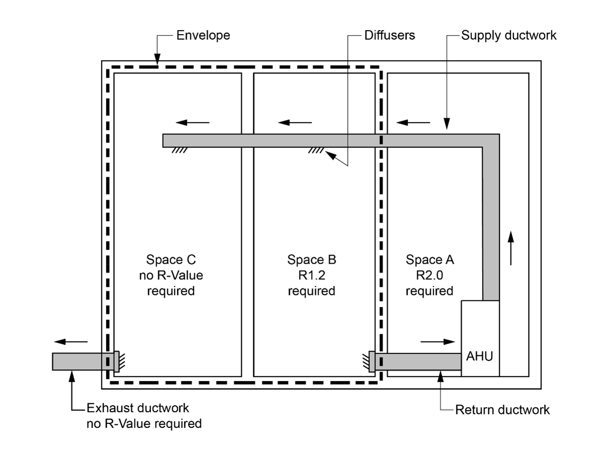
| Within a conditioned space | 1.2 | 2.0 |
| Where exposed to direct sunlight | 3.0 | 3.0 |
| All other locations | 2.0 | 3.0 |
Ductwork and fittings in an air-conditioning system need to be insulated to reduce energy loss. The insulating requirements do not apply to ventilation ductwork where the air is not heated or cooled.
J6D6(1)(a) outlines that insulation must comply with the requirements of AS/NZS 4859.1. J6D6(1)(b) specifies the minimum material R-Value of ductwork and fittings.
Note that the insulation levels in Table J6D6 are minimum material R-Values of the added insulation and are based on the location and climate zone of the installed ductwork and fittings.
J6D6(2) outlines specific requirements of the insulation, such as (a), that the insulation must be protected against the effects of weather and sunlight, which will likely reduce its insulating properties over time.
J6D6(2)(b) requires insulation to be installed so that it abuts adjoining insulation to form a continuous barrier as any gaps in the insulation allow heat loss or gain. The insulation should also maintain its position and thickness other than at flanges and supports as any compression of insulation can reduce its effectiveness.
J6D6(2)(c)(i) requires a vapour barrier to be installed around the insulation on ductwork that conveys cold air to assist in the control of condensation resulting from the cold surface. Without a vapour barrier, the likelihood of condensation forming increases. Condensing moisture can saturate the insulation, thereby reducing its effectiveness and causing it to deteriorate.
J6D6(2)(c)(ii) states that where the vapour barrier is used as a membrane, it must overlap by 50 mm and be bonded or taped together to ensure the vapour barrier membrane can function as intended.
J6D6(3) exempts a number of situations where ductwork and fittings do not need to be in accordance with the requirements of J6D6(1) as it may be impractical or pointless to do so.
J6D6(3)(a) exempts ductwork and fittings located within the only or last room served from being insulated on the basis that the heating or cooling effect is intended for that room anyway. If a room where the ductwork is not insulated is sub- divided then insulation will need to be added to the ductwork that passes through the first room to serve the second room. This needs to be considered if the exemption is applied to a part of a building or storey likely to be sub-divided as part of a fit-out.
J6D6(3)(b) exempts fittings that form the interface with the conditioned space such as air registers, diffusers, outlets, grilles and the like, as there would be minimal heat transfer occurring.
J6D6(3)(c) exempts return air ductwork in, or passing through, a conditioned space from meeting the minimum insulation requirements as there would be no heat transfer across the ductwork.
J6D6(3)(d) exempts ductwork containing unconditioned outside air or exhaust air ductwork where the air is to be discarded anyway. There would be no benefit gained, in terms of reducing energy consumption, by requiring insulation to be installed on this ductwork.
J6D6(3)(e) exempts the floor of an in-situ air handling unit from the insulation requirements of J6D6(1).
J6D6(3)(f) exempts air-conditioning equipment that complies with MEPS. Note that air-handling ductwork must also comply with S7C5.
The application of the ductwork insulation requirements are shown in the example shown at the end of this commentary (see Figure J6D6).
In this example:
J6D6(4) outlines that for the purposes of this Specification, ‘fittings’ includes passive or static components of a ductwork system and excludes active components of a ductwork system such as those used in an air-handling unit.
This means passive or static components of a ductwork system must meet the insulation requirements of this section and may include items such as plenums, bends, branches, transitions, reducers, offsets, spigots, cushion heads, attenuators and fixed air balance dampers.
Active components of a ductwork system are exempt from the insulation requirements of this section. This exemption recognises that there are practical difficulties applying insulation to components that move or where access is regularly required.
Active components may include Variable Air Volume (VAV) boxes, electric duct heaters, actuated volume control dampers, access panels and doors, fire and smoke dampers, fans or humidifiers.
Figure J6D6: Example – Application of ductwork insulation
Ductwork in an air-conditioning system with a capacity of 3000 L/s or greater, not located within the only or last room served by the system, must be sealed against air loss in accordance with the duct sealing requirements of AS 4254.1 and AS 4254.2 for the static pressure in the system.
Air-conditioning ductwork has joints, and unless sealed these joints will allow heated or cooled air to escape. To limit this heat loss or gain, ductwork must be sealed with adhesives, mastics, sealants, gaskets or the like in accordance with AS 4254 Parts 1 and 2 for the static pressure in the system. AS 4254 is the standard covering ductwork for air-handling systems in buildings. These requirements do not apply to ventilation ductwork where the air is not heated or cooled.
The requirements only apply to duct systems with a capacity of 3000 L/s or greater. The requirements do not apply to ductwork in the space being conditioned or the last room served by the system, as the air is intended for that space anyway.
The duct leakage tests of clause 2.2.4 of AS 4254.2 are included in this requirement. The key purpose of this is not so much to deal with minor leakage but to ensure that there are no major leaks such as uncapped spigots and similar in the system. Construction errors of this nature can cause leakage rates in excess of 20% in some systems, severely compromising system performance.
| Nominal pipe diameter (mm) | Maximum pressure drop in systems operating 5000 hours/annum or less (Pa/m) | Maximum pressure drop in systems operating more than 5000 hours/annum (Pa/m) |
|---|---|---|
| Not more than 20 | 400 | 400 |
| 25 | 400 | 400 |
| 32 | 400 | 400 |
| 40 | 400 | 400 |
| 50 | 400 | 350 |
| 65 | 400 | 350 |
| 80 | 400 | 350 |
| 100 | 400 | 200 |
| 125 | 400 | 200 |
| 150 or more | 400 | 200 |
| Nominal pipe diameter (mm) | Maximum pressure drop in systems operating 5000 hours/annum or less (Pa/m) | Maximum pressure drop in systems operating more than 5000 hours/annum (Pa/m) |
|---|---|---|
| Not more than 20 | 400 | 400 |
| 25 | 400 | 400 |
| 32 | 400 | 400 |
| 40 | 400 | 400 |
| 50 | 400 | 400 |
| 65 | 400 | 400 |
| 80 | 400 | 400 |
| 100 | 400 | 300 |
| 125 | 400 | 300 |
| 150 or more | 400 | 300 |
| Nominal pipe diameter (mm) | Maximum pressure drop in systems operating 2000 hours/annum or less (Pa/m) | Maximum pressure drop in systems operating between 2000 hours/annum and 5000 hrs/yr (Pa/m) | Maximum pressure drop in systems operating more than 5000 hours/annum (Pa/m) |
|---|---|---|---|
| Not more than 20 | 400 | 300 | 150 |
| 25 | 400 | 220 | 100 |
| 32 | 400 | 220 | 100 |
| 40 | 400 | 220 | 100 |
| 50 | 400 | 220 | 100 |
| 65 | 400 | 400 | 170 |
| 80 | 400 | 400 | 170 |
| 100 | 400 | 400 | 170 |
| 125 | 400 | 400 | 170 |
| 150 or more | 400 | 400 | 170 |
| Nominal pipe diameter (mm) | Maximum pressure drop in systems operating 5000 hours/annum or less (Pa/m) | Maximum pressure drop in systems operating more than 5000 hours/annum (Pa/m) |
|---|---|---|
| Not more than 20 | 400 | 250 |
| 25 | 400 | 180 |
| 32 | 400 | 180 |
| 40 | 400 | 180 |
| 50 | 400 | 180 |
| 65 | 400 | 300 |
| 80 | 400 | 300 |
| 100 | 400 | 300 |
| 125 | 400 | 300 |
| 150 or more | 400 | 300 |
There are two options for demonstrating that a pump system that forms part of an air-conditioning system is compliant with J6D8. The first option is to demonstrate that each of the individual components of a pump system are individually more efficient than the values specified in J6D8.The second option is to demonstrate that the pump system as a whole is more efficient than a system that is designed to meet the individual component requirements.
The component level compliance option is intended to allow for a simpler method to demonstrate compliance, allowing for a relatively simple comparison against a Deemed-to-Satisfy efficiency value for each component of the pump system. The system-level compliance option is intended to allow for increased flexibility when design constraints prevent the individual component level metrics from being met, without necessitating the use of a J1V3 calculation or another Performance Solution.
J6D8(1) outlines these two options– demonstrating compliance at either a pump system component level or a whole-of- pump-system level.
J6D8(1)(a) is the option for component-level compliance and requires compliance with J6D8(2), (3) and (4).
J6D8(1)(b) outlines the option for whole-of-system compliance, where the pump motor power per unit of flowrate (e.g. W/L/s) of the pump in the system as per the design must be lower than the pump motor power per unit of flowrate if the system was designed in accordance with J6D8(2), (3) and (4). If a pump system as a whole is compliant with J6D8(1)(b), it does not need to comply with J6D8(2), (3) or (4).
J6D8(2) nominates the efficiency requirements of circulator pumps that form part of an air-conditioning system. J6D8(2) is a requirement if the component-level compliance option of J6D8(1)(a) is used. The clause applies to glandless impeller pumps with a rated hydraulic power output of less than 2.5kW, used in a closed loop system. The clause nominates that the pump must have an energy efficiency index of less than or equal to 0.27 in accordance with European Union Commission Regulation No. 622/2012.
J6D8(3) nominates the efficiency requirements of other pumps that form part of an air-conditioning system. J6D8(3) is a requirement if the component-level compliance option of J6D8(1)(a) is used. The clause applies to pumps not covered by J6D8(2). The clause nominates that the pump must have a minimum efficiency index of greater than or equal to 0.4 in accordance with European Union Commission Regulation No. 547/2012.
J6D8(4) nominates the maximum allowable pressure losses of straight segments of pipework that form part of an air- conditioning system. J6D8(4) is a requirement if the component-level compliance option of J6D8(1)(a) is used.
J6D8(4)(a) nominates the allowable pressure losses attributable to straight segments of pipework in non-distributive pipework systems. A non-distributive pipework system is a pipework system that does not have branches and has a constant flowrate through the entire pipe network. Pressure losses for constant speed systems are nominated in Table J6D8a and pressure losses for variable speed systems are nominated in Table J6D8b.
J6D8(4)(b) nominates the allowable pressure losses attributable to straight segments of pipework in distributive pipework systems. Pressure losses for constant speed systems are nominated in Table J6D8c and pressure losses for variable speed systems are nominated in Table J6D8d.
J6D8(5)(a) specifies that the requirements of J6D8(4) do not apply to valves and fittings, as these are largely determined by functional requirements of the system.
J6D8(5)(b) specifies that the requirements of J6D8(4) do not apply to pipework with a velocity of 0.7 m/s or less.
| Fluid temperature | Minimum insulation R-Value nominal pipe diameter ≤ 40 mm | Minimum insulation R-Value — nominal pipe diameter > 40 mm and ≤ 80 mm | Minimum insulation R-Value — nominal pipe diameter between > 80 mm and ≤ 150 mm | Minimum insulation R-Value — nominal pipe diameter > 150 mm |
|---|---|---|---|---|
| Low temperature chilled — ≤ 2°C | 1.3 | 1.7 | 2.0 | 2.7 |
| Chilled — > 2°C but ≤ 20°C | 1.0 | 1.5 | 2.0 | 2.0 |
| Heated — > 30°C but ≤ 85°C | 1.7 | 1.7 | 1.7 | 1.7 |
| High Temperature heated — > 85°C | 2.7 | 2.7 | 2.7 | 2.7 |
| Fluid temperature range | Minimum insulation R-Value |
|---|---|
| Low temperature chilled — ≤ 2°C | 2.7 |
| Chilled — > 2°C but ≤ 20°C | 1.8 |
| Heated — > 30°C but ≤ 85°C | 3.0 |
| High temperature heated — > 85°C | 3.0 |
J6D9 requires piping, vessels, heat exchangers and tanks that contain heating and cooling fluids that are part of an air- conditioning system to be insulated. Heating fluids include heated water, steam and condensate and cooling fluids include refrigerant, chilled water, brines and glycol mixtures, but does not include condenser cooling water. Piping, vessels, heat exchangers and tanks that are covered by MEPS are exempt from these requirements.
Condenser cooling water is exempt from the minimum insulation requirements of this clause due to the limited temperature difference between the piping contents and the surrounding space. This means there would likely be smaller energy savings achieved compared to the costs of insulation in these circumstances. However, insulation may be installed for reasons other than energy efficiency such as for acoustics, or to minimise the risk of condensation forming.
J6D9(1)(a) states that insulation must comply with the requirements of AS/NZS 4859.1 which covers materials for the thermal insulation of buildings - general criteria and technical provisions.
J6D9(1)(b) and (c) outline that insulation requirements are located in—
J6D9(1)(d) outlines that insulation requirements apply to pressure relief piping within 500 mm of the connection to the air- conditioning system.
Note the R-Value is that of the insulation and not the Total R-Value of the pipe, air film and insulation. This approach is similar to ductwork insulation. Where piping has a significant inherent R-Value, it maybe subtracted from the material R- Value required. However, the inherent R-Value of most piping materials is not sufficient to satisfy the requirements in Table J6D9a.
The insulation types in guide Table J6D9 are typical examples of materials that can be used to insulate piping and are provided for guidance only. The R-Values are calculated in accordance with AS/NZS 4859.1 as per the requirement in J6D9(1)(a) and averaged over a number of nominal pipe diameters.
The insulation values in Table J6D9a are based on a nominal diameter of the water piping. The single required R-Value for each pipe diameter is intended to allow for straightforward installation on-site and compliance to be achieved.
Table J6D9b specifies the minimum insulation requirements for vessels, heat exchangers and tanks with the values specified based on the likely temperature of the fluid.
J6D9(2)(a) requires insulation to be protected from the effects of weather and sunlight, which may reduce its insulating properties. This protection may be achieved by ensuring that the insulation is enclosed in protective sheathing such as formed metal sheeting, external grade plastics or other similar material.
J6D9(2)(b) requires insulation to be able to with stand the temperatures within the piping, vessel, heat exchanger or tank, otherwise degradation of the insulation’s thermal performance may occur.
J6D9(3) requires insulation to be protected by a vapour barrier if the piping, heat exchanger or tank contains a cooling fluid. This is to reduce the likelihood of condensation problems arising that are created by the internal temperature of the piping, heat exchanger or tank being below the dew point of the external air.
J6D9(4) outlines circumstances when piping, vessels and heat exchangers are exempt from meeting the requirements of J6D9(1) and (2). This includes where it is located within the last space being heated or cooled as the heating or cooling effect is intended for that space anyway, or it is in a slab or panel that is specifically designed as a heating or cooling system, such as an in-slab or in-screed heating or cooling system. This is because the insulation would contradict the aim of the heating or cooling from the piping. J6D9(4)(c) and (d) exempt piping that is supplied as part of an item of plant such as a chiller or boiler or inside an item of plant such as an air-handling unit, fan-coil unit or the like.
| Insulation | R-Value |
| 13 mm of closed cell polymer | 0.6 |
| 19 mm of closed cell polymer | 0.9 |
| 25 mm of closed cell polymer | 1.3 |
| 25 mm of glasswool | 1.3 |
| Floor area of the conditioned space | W/m2 of floor area in climate zone 3 | W/m2 of floor area in climate zone 4 | W/m2 of floor area in climate zone 5 | W/m2 of floor area in climate zone 6 | W/m2 of floor area in climate zone 7 |
|---|---|---|---|---|---|
| ≤ 500 m2 | 50 | 60 | 55 | 65 | 70 |
| > 500 m2 | 40 | 50 | 45 | 55 | 60 |
The energy sources that may be used for heating a space directly are listed in J6D10(1) which also specifies that all forms of heating described in J6D10(1)(a) to (e) can be used in combination so as not to restrict heating to only one type. This clause recognises a combination of heating options may be the most appropriate and cost effective heating solution and may include a limited amount of electric resistance heating.
J6D10(1)(d) permits reclaimed heat from another process such as from a refrigeration plant, a co-generation plant, and bio-fuels to be used and this reclaimed energy can be used in conjunction with one or more heaters allowed under J6D10.
Electric heating can be used in specific circumstances only as outlined in J6D10(1)(e)(i) which allows a small amount of electric resistance heating, up to 10 W/m2 for climate zone 1 and 40 W/m2 for climate zone 2, for the floor area of the conditioned space. The small allowances recognise the likely limited heating required for these mild climates.
J6D10(1)(e)(i)(C) permits larger electric heating allowances in situations where reticulated gas is not available at the allotment boundary, recognising the likely limited heating options in areas where natural gas is not readily available. The maximum values are specified in Table J6D10 and are again climatezone based to recognise the limited heatingrequired in temperate climates, compared to cool climates.
J6D10(1)(e)(ii) allows a further exemption for relatively small electric heaters in climate zones 1 to 5 if the annual energy consumption for this heating is not more than 15 kWh/m2 of the floor area of the conditioned space.
J6D10(1)(e)(iii) places limits on the amount of reheat allowed for an in-duct heater.
J6D10(2) permits a small 1.2 kW electric heater in a bathroom of a Class 2, Class 3 or Class 9c aged care building. Typically, this would include small electric heaters such as a 3-in-1 heater, exhaust fan and light system. The heater must be fitted with a means to ensure it will not run excessively when the bathroom is not in use.
J6D10(3) is specifically for fixed outdoor heating and cooling appliances and requires that the appliance must be capable of automatic shutdown, which may be achieved by an outdoor temperature sensor, timer, motion detector or the like. This requirement aims to limit energy consumption when the service is not needed.
J6D10(4) specifies the efficiencies required for a gas fired heater that heats a space via water, such as a boiler. The minimum thermal efficiencies are based on the rated gas consumption of the boiler in terms of MJ/hour. There are a number of testing standards that can be used to demonstrate a unit’s gross thermal efficiency, including—
Whatever the test used, it is important that the test conditions mirror the expected typical operating conditions. This is especially important in regard to condensing boilers, where the inlet/outlet temperature of water will greatly impact the overall efficiency.
An air-conditioning system refrigerant chiller must comply with MEPS and the full load operation energy efficiency ratio and integrated part load energy efficiency ratio in Table J6D11a or Table J6D11b when determined in accordance with AHRI 551/591.
| Chiller type | Full load operation (Wr/Winput power) | Integrated part load (Wr/Winput power) |
|---|---|---|
| Air-cooled chiller with a capacity ≤ 528 kWr | 2.985 | 4.048 |
| Air-cooled chiller with a capacity > 528 kWr | 2.985 | 4.137 |
| Water-cooled positive displacement chiller with a capacity ≤ 264 kWr | 4.694 | 5.867 |
| Water-cooled positive displacement chiller with a capacity > 264 kWr but ≤ 528 kWr | 4.889 | 6.286 |
| Water-cooled positive displacement chiller with a capacity > 528 kWr but ≤ 1055 kWr | 5.334 | 6.519 |
| Water-cooled positive displacement chiller with a capacity > 1055 kWr but ≤ 2110 kWr | 5.800 | 6.770 |
| Water-cooled positive displacement chiller with a capacity > 2110 kWr | 6.286 | 7.041 |
| Water-cooled centrifugal chiller with a capacity ≤ 528 kWr | 5.771 | 6.401 |
| Water-cooled centrifugal chiller with a capacity > 528 kWr but ≤ 1055 kWr | 5.771 | 6.519 |
| Water-cooled centrifugal chiller with a capacity > 1055 kWr but ≤ 1407 kWr | 6.286 | 6.770 |
| Water-cooled centrifugal chiller with a capacity > 1407 kWr | 6.286 | 7.041 |
| Chiller type | Full load operation (Wr/Winput power) | Integrated part load (Wr/Winput power) |
|---|---|---|
| Air-cooled chiller with a capacity ≤ 528 kWr | 2.866 | 4.669 |
| Air-cooled chiller with a capacity > 528 kWr | 2.866 | 4.758 |
| Water-cooled positive displacement chiller with a capacity ≤ 264 kWr | 4.513 | 7.041 |
| Water-cooled positive displacement chiller with a capacity > 264 kWr but ≤ 528 kWr | 4.694 | 7.184 |
| Water-cooled positive displacement chiller with a capacity > 528 kWr but ≤ 1055 kWr | 5.177 | 8.001 |
| Water-cooled positive displacement chiller with a capacity > 1055 kWr but ≤ 2110 kWr | 5.633 | 8.586 |
| Water-cooled positive displacement chiller with a capacity > 2110 kWr | 6.018 | 9.264 |
| Water-cooled centrifugal chiller with a capacity ≤ 528 kWr | 5.065 | 8.001 |
| Water-cooled centrifugal chiller with a capacity > 528 kWr but ≤ 1055 kWr | 5.544 | 8.001 |
| Water-cooled centrifugal chiller with a capacity > 1055 kWr but ≤ 1407 kWr | 5.917 | 9.027 |
| Water-cooled centrifugal chiller with a capacity > 1407 kWr | 6.018 | 9.264 |
J6D11 covers the requirements for refrigerant chillers and specifies that are frigerant chiller that is part of an air-conditioning system must have an energy efficiency ratio complying with MEPS and Table J6D11a or Table J6d11b for both full load and integrated part load. The tables are similar to tables in ASHRAE 90.1 2016. Table J6D11a contains higher full-load performance values, intended to be applicable to chillers which are more likely to operate at full load, while Table J6D11b contains higher part-load performance values intended t be applicable to chillers which are more likely to operate at part load. A designer may choose whether to comply with Table J6D11a or Table J6D11b.
The energy efficiency ratio must be determined by testing in accordance with the American Air-Conditioning & Refrigeration Institute (AHRI) Standard AHRI 551/591. This standard requires chillers to be tested at full load and at a series of part loads, which are then integrated into a single number part-load efficiency.
Note that the use of flow and return temperatures applied during the testing of chillers to AHRI 551/591 (a 6°C flow and 12°C return) may not be appropriate to allow for a pumping system compliant with J6D8.
The European Union(EU) has developed a Minimum Energy Performance requirement for chillers used within its borders: EU Eco-design Lot 21. For equipment certified under this scheme a Performance Solution, showing how the chiller compares to Deemed-to-Satisfy requirements of J6D11, may be used with the approval of the local building control authority.
Unitary air-conditioning equipment including packaged air-conditioners, split systems, and variable refrigerant flow systems must comply with MEPS and for a capacity greater than or equal to 65 kWr—
A unitary air-conditioner is a modular factory assembled air-conditioning unit. These units are self-contained and include within the unit all the components for heating and/or cooling such as fans, controls, a refrigeration system, heating coil and sometimes the heater. Split systems, packaged air-conditioners, variable refrigerant flow and variable refrigerant volume air-conditioners are all types of unitary air-conditioners.
J6D12 states that unitary air-conditioning equipment with a capacity of less than 65 kW r must have a minimum energy efficiency ratio when cooling complying with MEPS.
J6D12(a) specifies the efficiency required for water-cooled packaged air-conditioning equipment.
J6D12(b) specifies the efficiency required for air-cooled packaged air-conditioning equipment.
AS/NZS 3823.1.2 has various test conditions so this clause requires the equipment to be tested at condition T1. This standard covers the performance of electrical appliances - air-conditioners and heat pumps, ducted air-conditioners and air-to-air heat pumps - testing and rating for performance.
| Type | Cooling tower maximum fan motor input power (W/kWrej) | Closed circuit cooler maximum fan motor input power (W/kWrej) | Evaporative condenser maximum fan motor input power (W/kWrej) |
|---|---|---|---|
| Induced draft | 10.4 | 16.9 | 11.0 |
| Forced draft | 19.5 | Note | 11.0 |
A closed circuit, forced draft cooling tower must not be used.
J6D13(1) outlines that the requirements for a fan, that is part of a cooling tower, closed circuit cooler or an evaporative cooler that is part of an air-conditioning system, are located in Table J6D13. The maximum fan motor power allowed is dependent on the type of fan used.
The performance of cooling tower fans, closed circuit cooler fans and evaporative condenser fans can be determined using any nationally or internationally accepted standard. For example Cooling Technology Institute’s (CTI) standard CTI STD-201RS(13) and Acceptance Testing Code (ATC) ATC-105(00), can be used to determine the performance of cooling tower fans. CTI STD-201RS(13) and ATC-105S(11) can be used for closed circuit cooler fans andATC-106(11) can be used to determine the performance of evaporative condenser fans.
J6D13(2) states the requirements for a self-contained, air-cooled condenser fan motor that is part of an air-conditioning system. The fan motor must not consume more than 42 watts of fan motor power for each kW of heat removed from the refrigerant. The air-cooled condenser fan is used to cool refrigerant from its vapour phase to its liquid phase as part of the refrigeration cycle.
Air-cooled condensers, not part of a packaged air-conditioner or split unit as per the exemptions in J6D13(2)(a) and (b), are typically associated with larger plant installations. The requirements of J6D13(2) are also not intended to capture a condenser covered by MEPS.