NCC 2022 Volume One - Building Code of Australia Class 2 to 9 buildings
Search the National Construction Code editions
8
Specification 8 Performance of external walls in fireThis Specification contains measures to minimise, in the event of fire, the likelihood of external walls covered by S8C2 collapsing outwards as complete panels and the likelihood of panels separating from supporting members.
To clarify that Specification 8 aims to minimise the risk, in a fire, of external walls collapsing outwards as complete panels and panels separating from supporting members.
Specification 8 contains detailed Deemed-to-Satisfy Provisions that could form part of a solution to achieve C1P5. These provisions include solutions to avoid the potential collapse outwards, as whole panels, of concrete external walls in a building with a rise in storeys of not more than 2, and minimum design loads which panel connections must resist during a fire.
This Specification applies to buildings having a rise in storeys of not more than 2 with concrete external walls that could collapse as complete panels (e.g. tilt-up and precast concrete) which—
To clarify that Specification 8 applies only to buildings with a raise in storeys of 2 or less, where those buildings have concrete external walls that could collapse as complete panels.
Specification 8 applies only to buildings with a rise in storeys of 2 or less, where the external walls are constructed using tilt-up and precast concrete panels.
Figure S8C2a
Typical non-loadbearing panels required to comply with Specification 8 (Panels may be full bay, multiple vertically or horizontally spanning)
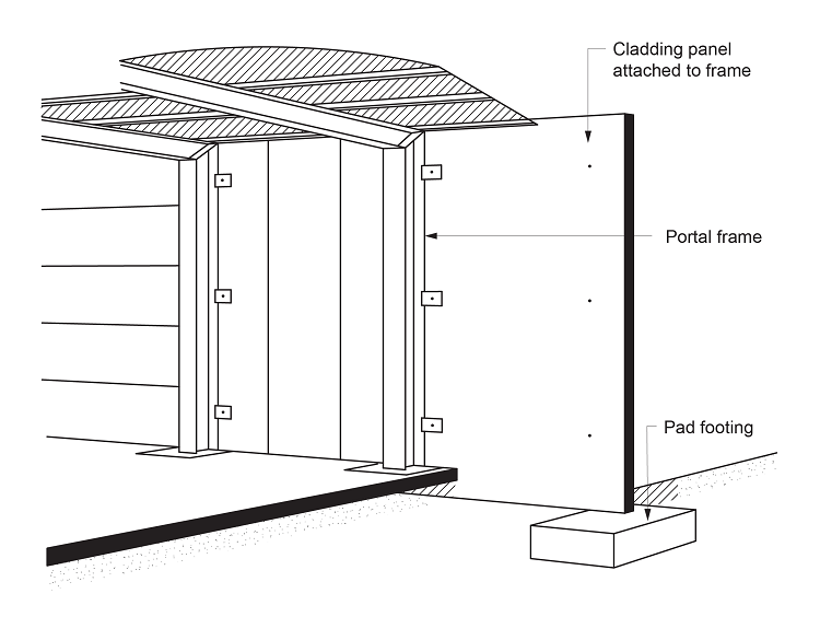
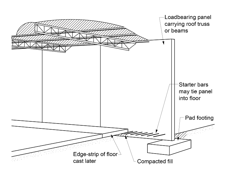
Figure S8C2b
Typical loadbearing panels required to comply with Specification 8
The increased forces specified by the multiplier of two or six in (2) and (3) above are to take account of the lower strength of the connections and members at the higher than ambient temperatures expected in a fire.
To provide general requirements for external wall panels which will minimise the risk of them collapsing in a fire and causing death and/or injury.
The concrete shear cone is the element of a panel that provides the bulk of the interconnection or fixing load capacity of the panel to the main structure. The aim of S8C3(1) is to provide some attachment to the panel after the concrete shear cone has failed during a fire. See Figure S8C3a.
S8C3(2) sets out the strength capacity required for top inserts or fixings so that the collapsing framework or roof structure will pull the panel inwards. See Figure S8C3b. The value for outward displacement of one tenth of the panel’s height is based on observations of deflections on buildings during a fire.
Drilled-in inserts and clips will suffer a greater strength loss from exposure to fire than cast-in inserts. The difference between the factor of two given in S8C3(2) and of six in S8C3(3) is based on engineering principles.
The lateral supporting members referred to in S8C3(4), for “tilt-up type buildings”, may be roof beams or trusses.
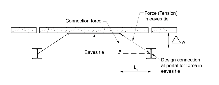
Where the wall panels are supported by eaves tie members, S8C3(4) requires that calculation of the forces in the eaves tie take into account the geometry of the deformations of the eaves tie. Figure S8C3c illustrates this requirement.
When applying the provisions of S8C3(5), panels used in a group have to be actually “designed to act as one unit”. It is not enough for the designer just to nominate the number of panels that are to act together.
While Specification 8 mostly applies to vertically spanning panels, S8C3(6) addresses specific provisions applicable to horizontally spanning panels.
Figure S8C3a
Typical anchor bars for inserts.
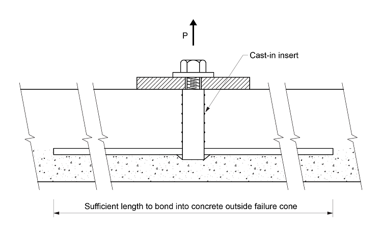
Figure S8C3b
Forces to pull panel inwards.
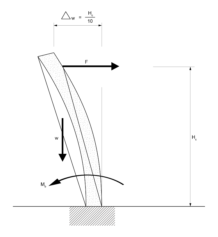
Figure S8C3c
Forces in eaves tie.
To provide some additional requirements to enhance the safety of vertically spanning external wall panels which are adjacent to columns.
Observation of the effects of fires shows that during a fire:
These results create large forces on fixings of concrete wall panels to steel columns. Accordingly, S8C4(1) requires that connections minimise the effect of such forces.
The provisions of S8C4(2) provide two means of complying with S8C4(1). However, they may not be the only means. S8C4(1) is a performance criterion.
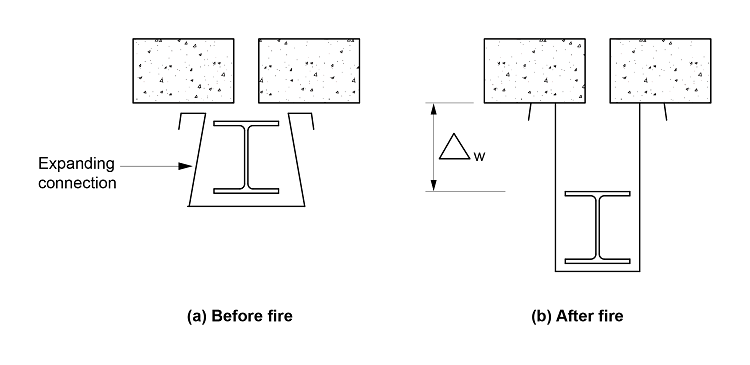
S8C4(2) provides two strategies for the designer to adopt to minimise fire induced forces on the means used to fix vertically spanning concrete wall panels to steel columns.
If the supporting framework is a material other than steel, such as concrete or timber, the differential deflections assumed by S8C4 will not occur, and the requirements of S8C4(2)(a) and (b) will be inappropriate.
S8C4(2)(a) suggests a design of a fixing that will accommodate the expected differential displacement. Figure S8C4 illustrates possible solutions to provide for the deflections. The magnitude of the differential deflection given in S8C4(2)(a)(i) and (ii) is based on observations of buildings under fire conditions.
The solution referred to in S8C4(2)(b) depends on fixing the concrete panel to the eaves tie member, and taking up the differential deflection in the eaves tie member. The distance this connection must be made away from the column is specified.
If this option is taken, the eaves tie member must be designed to comply with S8C3(4).
Figure S8C4
Typical fixing to accommodate differential deflection under fire.