NCC 2022 Volume One - Building Code of Australia Class 2 to 9 buildings
Search the National Construction Code editions
G2
Part G2 Boilers, pressure vessels, heating appliances, fireplaces, chimneys and fluesThis Part is intended to reduce the risk to building occupants from the operation, malfunction or failure of boilers, pressure vessels and combustion appliances including components such as fireplaces, chimneys, flues, chutes, hoppers and the like.
Part G2 does not contain requirements for gas heaters, gas appliances and associated flues.
The Objective of this Part is to—
Combustion appliances using controlled combustion located in a building are to be installed in a way which reduces the likelihood of fire spreading beyond the appliance.
G2F1 requires that a heating system be installed to prevent fire spreading to adjoining building elements.
A key expression in G2F1 is “controlled combustion”. This expression means that only heating units which burn solid materials or oil must comply with these provisions. The expression applies to open fireplaces, oil heaters, solid-fuel burning stoves, coal heaters, pot-belly stoves, and other such cooking and heating devices.
The expression does not include electric heaters. Nor is it intended to include gas heaters covered by other State and Territory legislation.
Boilers and pressure vessels located in a building are to be installed in a manner which will provide adequate safety for occupants.
Additional measures must be taken when a boiler or pressure vessel is installed in a building, due to the potential damage and injury which may be caused by a malfunction.
Where provided in a building, a combustion appliance and its associated components, including an open fire-place, chimney, flue, chute, hopper or the like, must be installed—
When installed in a building, a combustion appliance (including all associated components) must be:
When located in a building, boilers and pressure vessels must be installed to avoid, during reasonably foreseeable conditions, the likelihood of—
Because of the dangers of boilers and pressure vessels, care has to be taken during installation. Boilers and pressure vessels located outside a building are not covered by the BCA, but may be controlled by other State and Territory legislation.
Issues such as leakage of pressurised liquids and the consequences of the vessel being damaged must be considered. Damage must be avoided to the vessel. Such damage could occur if the vessel is located in an area subject to traffic.
Compliance with G2P1(a) and G2P1(b) is verified when—
Under G2V1, it needs to be demonstrated that the proposed appliance will not deteriorate under standard operating conditions. Examples of deterioration may include deformation or failure of components that would render the appliance unsafe to use.
For the purposes of demonstrating compliance with (a), the typical operating temperature of a combustion device can be established by testing.
For the purposes of demonstrating compliance with (b), materials used for building elements (walls, floors and ceiling) in the areas surrounding an appliance can be appropriately selected and/or designed to align with the quantified values as determined by (a). This could either be achieved by using the expert judgement of an engineer or by adhering to manufacturer’s specifications. Certification in accordance with CodeMark Australia would also be a possibility in demonstrating compliance using the Verification Method. Full range of thermal movements relates to both the appliance and materials when exposed to both the heated and ambient conditions.
Benefits to industry derived from the application of this Verification Method include the potential use of non-standard national or internationally manufactured appliances. For example, test reports for appliances complying with various ISO Standards and various British Standards could be used to demonstrate compliance with the Verification Method. The Verification Method also allows for in-situ testing of unique combustion appliances, which would not easily be tested in accordance with the Australian Standard. Such testing would need to be verified by a suitably qualified practitioner and be supported by appropriate documentation.
To clarify that requirements of G2P1 and G2P2 will be satisfied if compliance is achieved with G2D2 to G2D4.
Where a solution is proposed to comply with the Deemed-to-Satisfy Provisions, G2D1 clarifies that compliance with G2D2 to G2D4 achieves compliance with G2P1 and G2P2.
Where a Performance Solution is proposed, the relevant Performance Requirements must be determined in accordance with A2G2(3) and A2G4(3) as applicable. (See commentary on Part A2).
The installation of a stove, heater or similar appliance in a building must comply with:
To specify the Australian Standards which are suitable to achieve compliance with G2P1 and G2P2 as regards the installation of domestic solid-fuel burning appliances, pressure equipment and the like.
Solid-fuel burning appliances and pressure equipment
G2D2 lists one standard as a Deemed-to-Satisfy Provision for the installation of domestic solid-fuel burning appliances (see G2D2(a)), and for boilers and pressure vessels G2D2 refers to Specification 30.
The requirements of G2D2 limits the requirements to stove, heater or similar appliance in a building. Therefore, the provision does not apply to boilers and pressure vessels outside of these limitations, such as portable gas appliances.
An open fireplace, or solid-fuel burning appliance in which the fuel-burning compartment is not enclosed, must have—
To provide for the safe design and installation of open fireplaces.
G2D3 relates to open fireplaces where timber or other solid material is burned and there is generally no in-built enclosing structure or apparatus across the front to contain sparks, etc.
The construction of a fireplace must comply with the structural requirements in Section B of the NCC. The G2D3 requirements relate to additional measures for fire safety.
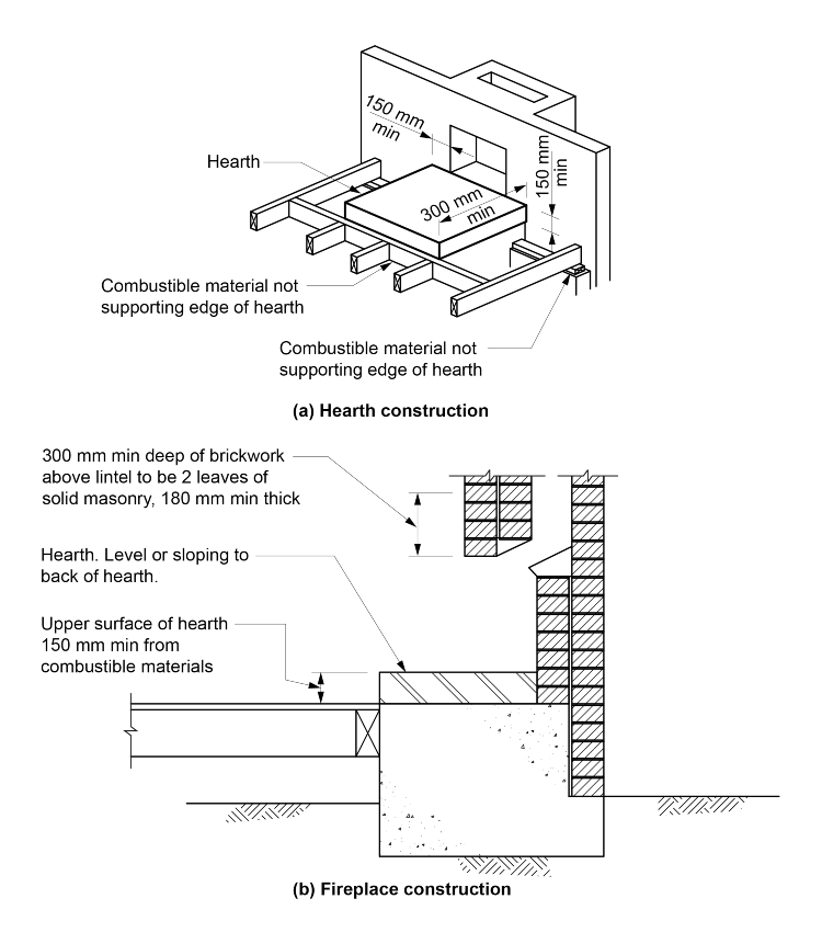
G2D3(a) states that the fireplace must have a hearth made of stone, concrete or other similar non-combustible material. The non-combustible material must be similar in nature to stone and concrete. The concessions for non-combustible material in Section C of the NCC, particularly C2D10 (such as plasterboard and similar lightweight materials), must not be construed as complying with these specific provisions.
With the increased danger due to the open-fire area, G2D3(a) contains requirements to ensure the area in front of the opening is protected. The hearth is intended not only to protect adjoining building elements from sparks, but also to reduce the danger of logs rolling out. See Figure G2D3.
G2D3(b) deals with the construction of a fireplace (additional to the requirements of Section B). These relate to the fire box and the need to ensure that the walls adjacent to the fire can withstand the heat. Concrete blockwork is not allowed to form the fire box because it performs poorly under repeated heating and cooling cycles.
G2D3(c) contains the requirements for chimneys.
G2D3(c)(i) aims to make sure the masonry of a chimney is capable of withstanding heat. The construction requirements are less than those for the firebox, because the most intense area of the fire is below the actual level of the chimney.
G2D3(c)(ii) contains a requirement to line the chimney with a rendering mix to make sure it draws properly. A smoother surface:
G2D3(d) contains a requirement to ensure that damp-proof courses and flashings are installed.
Figure G2D3: Fireplace clearance from combustible materials
To provide requirements for the safe installation of an incinerator room in a building.
Incinerators, hoppers and incinerator rooms
G2D4(1) contains requirements for incinerators and their hoppers. “Hopper” refers to the area used to feed the incinerator. The requirements for hoppers aim to make sure they do not increase the risk of fire to the adjoining building area.
G2D4(1)(e) states that a hopper must not be located in a required exit. This is to prevent any potential problem where a failure in the hopper could affect the egress route.
G2D4(2) requires an incinerator to be fire separated from the remainder of the building.