NCC 2022 Volume One - Building Code of Australia Class 2 to 9 buildings
Search the National Construction Code editions
21
Specification 21 Smoke exhaust systemsThis Specification describes the requirements for mechanical smoke exhaust systems.
To state that Specification 21 outlines the requirements for mechanical smoke exhaust systems.
Mechanical smoke exhaust systems
Specification 21 contains the requirements for mechanical smoke exhaust systems.

To specify the capacity and exhaust rates required of mechanical smoke exhaust systems.
Height below the smoke layer—S21C2(1)
S21C2(1) defines the height to be maintained to the underside of the smoke layer. This height is used to determine the smoke exhaust capacity for various design fires under steady state conditions.
Exhaust rates—S21C2(2)
S21C2(2) requires exhaust rates be determined using Figure S21C2 of Specification 21. It specifies the exhaust rate required relative to the height to the underside of the smoke layer for various fire loads determined using Table S21C2.
How to use Figure S21C2
The following needs to be known to use Figure S21C2:
Smoke exhaust rates
The smoke exhaust rate in Figure S21C2 is based on the rate at which air is drawn (i.e. “entrained”) into a plume of smoke which is generally symmetrical around a vertical axis where that plume is rising into the hot layer formed by the smoke reservoir.
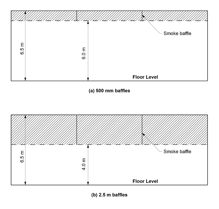
The height to the underside of the smoke layer is measured from the highest floor level to the underside of the smoke reservoir. The smoke reservoir’s depth is determined by the depth of the smoke baffles/curtains required by S21C4. See Guide Figure S21C2.
Figure S21C2
Method of measurement of height to the underside of smoke layer.
Each smoke exhaust fan, complete with its drive, flexible connections, control gear and wiring must—
To specify the operational requirements for smoke exhaust fans.
Operational requirements for smoke exhaust fans
S21C3describes the operational requirements for smoke exhaust fans to ensure their design performance is maintained for an appropriate time, when operating in high temperature conditions. Fans must also be rated for ambient temperature operation to facilitate routine maintenance. These provisions also apply to dual purpose fans, that is those used for normal air-handling operations as well as for smoke exhaust.
To specify the requirements for smoke reservoirs, to enable the containment of smoke in the upper levels of compartments.
Smoke reservoirs—S21C4(1)
S21C4(1) requires the division of fire compartments into smoke reservoirs.
Smoke reservoirs are necessary to contain the hot layer in the upper levels of compartments, thus preventing the lateral spread of smoke resulting in excessive cooling and downward mixing of the smoke with the relatively clear layer below which:
Horizontal area to be less than 2000 m2—S21C4(2)
To maximise the effectiveness of smoke reservoirs, the horizontal area formed by a reservoir is limited by S21C4(2) to 2000 m2.
Maximum length in a shopping mall—S21C4(2)
The maximum length of a smoke reservoir in a shopping mall is limited by S21C4(2) to 60 metres, due to the distance people would be expected to travel below a smoke layer while evacuating to a safe place, having regard to the potential for smoke, from a fire in a mall or adjacent specialty shop, to flow into more than one reservoir.
Depth—S21C4(3)
S21C4(3) specifies that the smoke reservoir must be of “sufficient” depth to contain the smoke layer.
Bulkhead or smoke baffle—S21C4(4)
S21C4(4) deals with the location and depth of a bulkhead or smoke baffle/curtain. Any bulkhead and smoke baffle/curtain must be non-combustible. S21C4(4) applies only to multi-storey fire compartments.
Smoke needs to be contained within the floor reservoir, and so the integrity of the containment must be maintained at the edges of voids in buildings, such as atriums, by the provision of non-combustible bulkheads or baffles.
Smoke exhaust fans and vents must be located—
To make sure that exhaust fans and vents do not draw clean air up through the smoke layer.
Prevention of “plug-holing”
For a given depth of smoke layer, there is a maximum rate at which smoke can be extracted from a single inlet before air is drawn from below the smoke layer. This is sometimes referred to as “plug-holing”.
Where the smoke layer is relatively shallow, more than one extraction point may be needed to minimise “plug-holing”. It may also be necessary to distribute the extraction points to prevent the formation of stagnant regions leading to excessive cooling and downward mixing of smoke with the relatively clear air below.
Suitable discharge location
It is not suitable for a smoke exhaust fan and vent to discharge adjacent to an occupiable outdoor area. Specific criteria are not given as the design is dependent on actual building layout.
To provide air to replace that being exhausted by the smoke exhaust system.
Maintenance of the smoke layer—S21C6(1)
It is necessary to introduce “make-up air” to replace the air being exhausted by the smoke exhaust system, to:
Low velocity—S21C6(2)
Make-up air introduced below the smoke layer must be at relatively low velocities, to minimise any disturbance to the smoke layer. Make-up air introduced at higher velocities may cause:
Multi-storey fire compartments—S21C6(3)
S21C6(3) deals with the provision of make-up air across any vertical opening from the building void to the fire-affected storey. This aims to minimise the risk of smoke spreading from the fire-affected storey to other storeys.
Non-prescriptive provisions
Specific criteria are not given in S21C6 as the design is dependent on actual building layout.
To specify the control requirements for smoke exhaust systems and automatic make-up air arrangements.
Sequential activation—S21C7(1)
To make sure that the smoke exhaust fan (or fans) operate in the designed manner, S21C7(1) requires that the fans are activated sequentially by smoke detectors, and arranged in zones to match the smoke reservoir served by the fan (or fans).
Automatic shutdown—S21C7(2)
S21C7(2) requires air handling systems (which generally supply air to upper storeys in high rise buildings) to shut down on the activation of the smoke exhaust system where the air handling system:
• does not form part of the smoke hazard management system;
• is not an individual room unit operating at a rate of less than 1000 L/s; or
• is not a miscellaneous exhaust air system installed in accordance with Sections 5 and 6 of AS 1668.1.
This requirement minimises any disturbance to the hot smoke layer and limits smoke being distributed to other non-fire- affected areas of the building by way of the system.
S21C7(2) is subject to S21C7(3) and (4).
Concessions—S21C7(3) and (4)
A number of additional concessions to S21C7(2) are allowed, including:
• S21C7(3)—systems supplying a single storey fire compartment may supply 100 per cent outside air to the non-fire- affected areas as a means of supplying make-up air for the extraction system serving fire-affected areas; and
• S21C7(4)—systems supplying a multi-storey fire compartment must supply 100 per cent outside air to the non-fire- affected areas as a means of supplying make-up air for the extraction system serving fire-affected areas.
Override control—S21C7(5) and (6)
To allow manual control of the smoke exhaust system by the fire brigade, S21C7(5) requires an override control to be located adjacent to the fire indicator panel.
In a theatre, an additional manual control must be provided in accordance with S21C7(6) to allow the stage manager to control the smoke exhaust system during a performance. This is considered necessary because of any special effects which may cause a false alarm.
Electric cabling—S21C7(7)
To reduce the risk of the smoke exhaust system failing during a fire, S21C7(7) requires the electric cabling to the system’s essential components to be protected from fire in accordance with AS 1668.1.
A smoke detection system must be installed in accordance with Specification 20 to activate the smoke exhaust system.
To clarify the location of the requirements for the installation of a smoke detection system.
The smoke detection requirements for smoke exhaust systems are addressed in S21C5. Such smoke detection systems designed to operate smoke-and-heat vents must also activate an occupant warning system. Specification 20 provides the installation and operation requirements for automatic smoke detection and alarm systems.