NCC 2022 Volume One - Building Code of Australia Class 2 to 9 buildings
Search the National Construction Code editions
J4
Part J4 Building fabricThis Part contains Deemed-to-Satisfy Provisions for compliance with Part J1. It sets out provisions for the building envelope including roofs, ceilings, roof lights, walls, glazing and floors.
From 1 May 2023 to 30 September 2023 Section J of NCC 2019 Volume One Amendment 1 may apply instead of Section J of NCC 2022 Volume One. From 1 October 2023 Section J of NCC 2022 Volume One applies.
In Tasmania, for a Class 2 building and Class 4 part of a building, Section J is replaced with Section J of BCA 2019 Amendment 1.
See comments for J2D1.
The Deemed-to-Satisfy Provisions of this Part apply to building elements forming the envelope of a Class 2 to 9 building other than J4D3(5), J4D4, J4D5, J4D6 and J4D7 which do not apply to a Class 2 sole-occupancy unit or a Class 4 part of a building.
To facilitate the efficient use of energy appropriate for Class 2 to 9 buildings that are conditioned or likely to be conditioned.
The Deemed-to-Satisfy Provisions of Part J4 apply to building elements that form part of the envelope, where the envelope separates a conditioned space or habitable room from the exterior of the building or a non-conditioned space. This includes roofs, walls, glazing and floors as per the definition of “fabric”.
Some Class 6, 7, 8 and 9b buildings that are not a conditioned space by definition may be excluded from controls for building fabric. Class 6 and 9b buildings cover a wide range of uses and some could reasonably be expected to be air- conditioned at some time in the future while others may not. For example, it may be unlikely that a school gymnasium will be air-conditioned while classrooms may well be when funds are available. Some States are already retrofitting air- conditioning to schools. Note that the phrase “likely by the intended use of the space to be air-conditioned” is in the definition of a conditioned space.
The external elements of an atrium or solarium that is not a conditioned space may also be excluded. The atrium may be attached to a Class 5 building and would otherwise attract some of the requirements appropriate for a Class 5 building. Again, either there is no energy saving to be made by thermally treating the elements, or the saving is below the minimum threshold and so not cost-effective.
The Deemed-to-Satisfy Provisions of Part J4 do not apply to Class 8 electricity network substations as these buildings are not required to be air-conditioned for the purposes of Section J. See the definition for air-conditioning. The air-conditioning systems of these buildings are instead designed to maintain the efficient operation of sensitive electrical equipment.
Where required is deemed to refer to “Where a development consent specifies that insulation is to be provided as part of the development.”.
To outline the general requirements to insulate a building’s fabric and the inherent thermal properties of roof, ceiling, wall and floor materials.
J4D3(1) requires that insulation must be tested and labelled in accordance with AS/NZS 4859.1.
Installation
Care should be taken when installing insulation to ensure a continuous envelope between a conditioned space and either the outside environment or a non-conditioned space.
Insulation is to be fitted tightly to each side of framing members but need not be continuous over the framing member.
The insulation requirements in J4D4, J4D6 and J4D7 are calculated for parts of the roof, walls or floor that are clear of any framing members. The means of achieving the required total R-Value must be in accordance with J4D3(5).
The provisions also state that the installation of insulation should not interfere with the safety or performance of domestic services and fittings such as heating flues, recessed light fittings, transformers for low voltage lighting, gas appliances and general plumbing and electrical components. This includes providing appropriate clearance as detailed in relevant legislation and referenced standards such as for electrical, gas and fuel oil installations. Low voltage lighting transformers should not be covered by insulation and be mounted above the insulation rather than on the ceiling. Expert advice may also be needed on how much bulk insulation can be placed over electrical wiring.
Note that the addition of insulation to other building elements may alter the fire properties of those elements. Re-testing or re-appraisal of these elements may be required.
For reflective insulation to achieve its tested R-Value, the airspace adjoining the insulation needs to be a certain width. This width varies depending on the particular type of reflective insulation and the R-Value to be achieved.
Where the width of airspace is to be achieved in a wall cavity or the like, care should be taken to ensure compliance with all other applicable BCA provisions. For example, the provisions relating to weatherproofing masonry may require a greater width of cavity.
The R-Value of bulk insulation is reduced if it is compressed. The allocated space for bulk insulation is therefore to allow the insulation to be installed so that it maintains its correct thickness unless exempted such as at wall studs. This is particularly relevant to wall and cathedral ceiling framing whose members can only accommodate a limited thickness of insulation. In some instances, larger framing members or thinner insulation material, may be necessary to ensure that the insulation achieves its required R-Value.
Artificial cooling of buildings in some climates can cause condensation to form inside the layers of the building envelope. Such condensation can cause significant structural or cosmetic damage to the envelope before it is detected. Associated mould growth may also create health risks to the occupants. Effective control of condensation is a complex issue. In some locations a fully sealed vapour barrier may need to be installed on the more humid, or generally warmer, side of the insulation.
A thermal bridge, also called a cold bridge or heat bridge, is an area or component of the fabric which has higher thermal conductivity than the surrounding materials, creating a path of least resistance for heat transfer. Thermal bridges can significantly reduce the thermal performance of a facade, increasing energy use from a building’s heating and cooling systems. If not accounted for, they can also cause unwanted condensation and comfort issues in a building. In line with the existing requirements of AS/NZS 4859.1, J4D3(5) specifies that the means of achieving the required Total R-Value must be determined in accordance with AS/NZS 4859.2. This standard contains a calculation method that takes into account the impact of thermal bridges on the thermal performances of a facade. Depending on the extent of the thermal bridges within a facade, extra insulation may need to be added, or thermal breaks installed in order for a facade to be compliant.
To clarify the minimum Total R-Value that is to be achieved by a roof or ceiling, according to the building classification and climate zone in which it is located.
J4D4 covers roofs, including their ceilings, and any ceiling that is part of an intermediate floor being part of the building’s envelope, or where there is no ceiling.
J4D4(1) details the insulation properties and minimum Total R-Value required of a roof or ceiling.
Part or all of this may be provided by the roof construction itself and any inherent insulating property of the roof and airspaces reduces the amount of insulation needed.
Where the ceiling space below the roof is used as the return air plenum, it is considered part of the conditioned space. In this instance, the envelope boundary for the roof and ceiling construction is located at the roof.
The direction of heat flow stated should not be taken as the only direction in which any insulating properties operate but it is a statement of the prominent direction for that particular climate zone. It is assumed that materials, be they construction materials or insulating materials, will also have insulating properties in the other direction. For a residential building, the night time direction is important as the building is most likely to be occupied at that time and the outside temperature likely to be the lowest of the day.
The Total R-Value in J4D4(1) is dependent on the climate zone.
As with walls, the effect of thermal bridging must be taken into account when determining if the minimum R-Value of a roof has been achieved. In some cases, thermal breaks will be necessary to achieve compliance.
A thermal break may be provided by materials such as timber or expanded polystyrene strips, plywood or bulk insulation. Reflective insulation alone is not suitable for use as a thermal break because it requires an adjoining airspace to achieve the specified R-Value.
The weight of roof or ceiling insulation needs to be considered in the selection of plasterboard, plasterboard fixings and building framing.
There may be instances where there is a loss of ceiling insulation because of downlights, fans and other penetrations. In these circumstances it is the responsibility of designers to determine how they will achieve the required Total R-Value given the construction of the roof and the penetrations.
Details of the Total R-Values of typical constructions are provided in Figures J4D4a to J4D4g and Tables J4D4a to J4D4g.
The Total R-Value of the basic roof and ceiling has been determined by adding together the material R-Values of the outdoor air film, roof cladding, roof airspace, ceiling sheet lining and internal air film.
The Total R-Value of the roof and ceiling materials may need to be adjusted if other building elements, such as sarking, are to also be installed.
Note that it should not be assumed that these figures are representative of all construction scenarios. For example the spacing of framing members, the presence of roof lights or the specific type of frame could all affect the actual Total R- Value by creating thermal bridging between elements or by compressing insulation. If following a Deemed-to-Satisfy compliance pathway, the code requires in J4D3(5) that AS/NZ 4859.2 be used to calculate the Total R-Value of a building’s envelope.
Insulation can be installed in the roof, the ceiling, or a combination of both, provided the required thermal performance is achieved and other aspects of the building’s integrity are not compromised. It should be noted that the thermal performance of the roof may vary depending on the position of the insulation, the climatic conditions, the design of the building and the way in which it is operated. For example, althoughnot recognised in the values,insulation installed underthe roof, rather than on the ceiling,in a building with a large roof space in a cold climate, or when a room is being air-conditioned, may be less effective because of the additional volume of roof airspace that would need to be heated or cooled.
For a material that is not listed as an item in the figure below, other than air, the R-Value may be determined by dividing the thickness of the item in metres by the thermal conductivity in W/m.K (typical values are described in Specification 36).
There are a number of different insulation products that may be used to achieve the minimum added R-Value. Care should be taken to ensure that the choice made is appropriate for the construction and climate conditions. For instance, in some climate zones, an impermeable insulation sheet needs to be installed with due consideration of condensation and associated interaction with adjoining building materials.
Figure J4D4a: Roof 15° to 45° pitch—horizontal ceiling—metal cladding
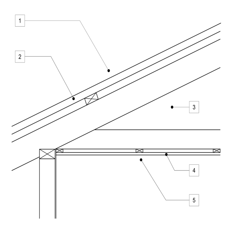
| Item no. | Description | R-Value unventilated | R-Value ventilated | ||
| Up | Down | Up | Down | ||
| 1. | Outdoor air film(7 m/s) | 0.04 | 0.04 | 0.04 | 0.04 |
| 2. | Metal cladding | 0.00 | 0.00 | 0.00 | 0.00 |
| 3. | Roof airspace (non-reflective) | 0.18 | 0.28 | 0.00 | 0.46 |
| 4. | Plasterboard gypsum (10 mm, 880 kg/m3) | 0.06 | 0.06 | 0.06 | 0.06 |
| 5. | Indoor air film(still air) | 0.11 | 0.16 | 0.11 | 0.16 |
| Total R-Value | 0.39 | 0.54 | 0.21 | 0.72 |
Figure J4D4b: Roof 15° to 45° pitch—horizontal ceiling—clay tiles 19 mm
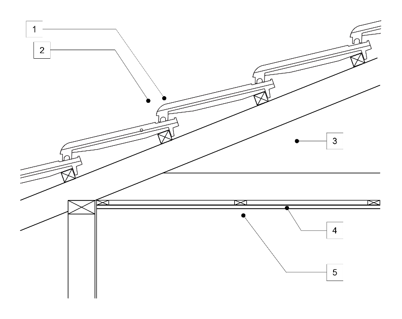
| Item no. | Description | R-Value unventilated | R-Value ventilated | ||
| Up | Down | Up | Down | ||
| 1. | Outdoor air film(7 m/s) | 0.04 | 0.04 | 0.04 | 0.04 |
| 2. | Roof tile, clay or concrete (1922 kg/m3) | 0.02 | 0.02 | 0.02 | 0.02 |
| 3. | Roof airspace (non-reflective) | 0.18 | 0.28 | 0.00 | 0.46 |
| 4. | Plasterboard gypsum (10 mm, 880 kg/m3) | 0.06 | 0.06 | 0.06 | 0.06 |
| 5. | Indoor air film(still air) | 0.11 | 0.16 | 0.11 | 0.16 |
| Total R-Value | 0.41 | 0.56 | 0.23 | 0.74 |
Figure J4D4c: Roof 15° to 45° pitch—cathedral ceiling—10 mm plaster on top of rafters—metal external cladding
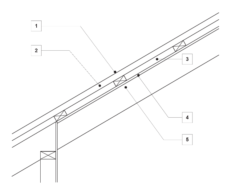
| Item no. | Description | R-Value unventilated | |
| Up | Down | ||
| 1. | Outdoor airfilm (7 m/s) | 0.04 | 0.04 |
| 2. | Metal cladding | 0.00 | 0.00 |
| 3. | Roof airspace (30 mm to 100 mm, non-reflective) | 0.15 | 0.18 |
| 4. | Plasterboard gypsum(10 mm, 880 kg/m3) | 0.06 | 0.06 |
| 5. | Indoor air film (still air) | 0.11 | 0.16 |
| Total R-Value | 0.36 | 0.42 | |
Figure J4D4d: Roof 15° to 45° pitch—cathedral ceiling—10 mm plaster on top of rafters—tiles external cladding
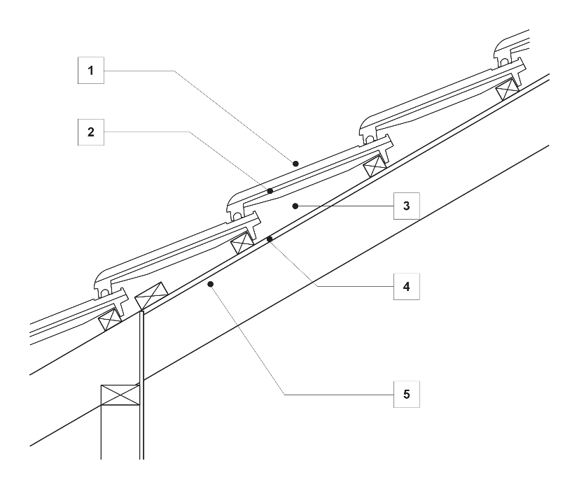
| Item no. | Description | R-Value unventilated | |
| Up | Down | ||
| 1. | Outdoor airfilm (7 m/s) | 0.04 | 0.04 |
| 2. | Roof tile, clay or concrete (1922 kg/m3) | 0.02 | 0.02 |
| 3. | Roof airspace (30 mm to 100 mm, non-reflective) | 0.15 | 0.18 |
| 4. | Plasterboard gypsum(10 mm, 880 kg/m3) | 0.06 | 0.06 |
| 5. | Indoor air film (still air) | 0.11 | 0.16 |
| Total R-Value | 0.38 | 0.44 | |
Figure J4D4e: Skillion roof less than 5° pitch—10 mm plaster below rafters—metal external cladding
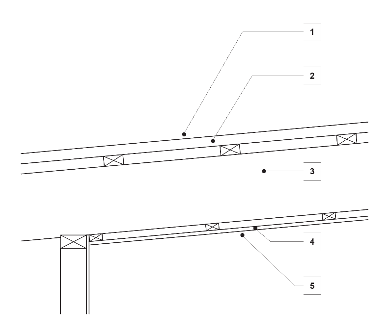
| Item no. | Description | R-Value unventilated | |
| Up | Down | ||
| 1. | Outdoor airfilm (7 m/s) | 0.04 | 0.04 |
| 2. | Metal cladding | 0.00 | 0.00 |
| 3. | Roof airspace (30 mm to 100 mm, non-reflective) | 0.15 | 0.22 |
| 4. | Plasterboard gypsum(10 mm, 880 kg/m3) | 0.06 | 0.06 |
| 5. | Indoor air film (still air) | 0.11 | 0.16 |
| Total R-Value | 0.36 | 0.48 | |
Figure J4D4f: Skillion roof 5° to 15° pitch—10 mm plaster on top of rafters—metal external cladding
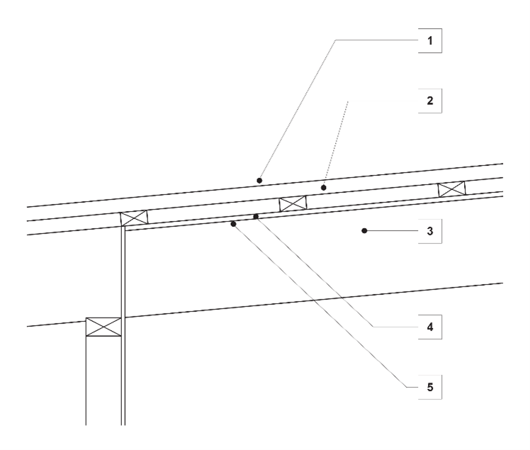
| Item no. | Description | R-Value | |
| Up | Down | ||
| 1. | Indoor air film(still air) | 0.11 | 0.16 |
| 2. | Solid concrete (150 mm, 2400kg/m3) | 0.10 | 0.10 |
| 3. | Ground thermal resistance | - | - |
| Total R-Value | 0.18 | 0.23 | |
Figure J4D4g: 100 mm solid concrete roof to 5° pitch—10 mm plaster suspended ceiling—applied ex- ternal waterproof membrane
| Item no. | Description | R-Value unventilated | |
| Up | Down | ||
| 1. | Outdoor airfilm (7 m/s) | 0.04 | 0.04 |
| 2. | Waterproof membrane, rubber synthetic (4 mm, 961kg/m3) | 0.03 | 0.03 |
| 3. | Solid concrete (100 mm, 2400kg/m3) | 0.07 | 0.07 |
| 4. | Ceiling airspace (100 mm to 300 mm, non-reflective) | 0.15 | 0.22 |
| 5. | Plasterboard gypsum (10 mm, 880 kg/m3) | 0.06 | 0.06 |
| 6. | Indoor air film (still air) | 0.11 | 0.16 |
| Total R-Value | 0.46 | 0.58 | |
Roof lights must have—
| Roof light shaft index Note 1 | Total area of roof lights up to 3.5% of the floor area of the room or space | Total area of roof lights more than 3.5% and up to 5% of the floor area of the room or space |
|---|---|---|
| <1.0 | ≤ 0.45 | ≤ 0.29 |
| ≥ 1.0 to < 2.5 | ≤ 0.51 | ≤ 0.33 |
| ≥ 2.5 | ≤ 0.76 | ≤ 0.49 |
To specify requirements for roof lights and provide a reasonable distribution of the roof lights.
J4D5 has values for Total System SHGC and Total System U-Values, which are expressed in accordance with the Australian Fenestration Rating Council (AFRC) protocol.
The provisions of J4D5(b)(i) require roof lights that form part of the envelope, other than of a sole-occupancy unit of a Class 2 building or a Class 4 part of a building, comply with Table J4D5.
The size of roof lights is limited to no more than 5% of the floor area of the space served in order to ensure that the thermal performance of a roof is not compromised to too great an extent. Larger roof lights will need to achieve compliance through a Verification Method or as a Performance Solution.
Table J4D5 provides the Total System SHGC requirements that satisfy J4D5(a).
| Climate zone | Class 5, 6, 7, 8 or 9b building or a Class 9a building other than a ward area | Class 3 or 9c building or Class 9a ward area |
|---|---|---|
| 1 | 2.4 | 3.3 |
| 2 | 1.4 | 1.4 |
| 3 | 1.4 | 3.3 |
| 4 | 1.4 | 2.8 |
| 5 | 1.4 | 1.4 |
| 6 | 1.4 | 2.8 |
| 7 | 1.4 | 2.8 |
| 8 | 1.4 | 3.8 |
| Climate zone | Eastern aspect solar admittance | Northern aspect solar admittance | Southern aspect solar admittance | Western aspect solar admittance |
|---|---|---|---|---|
| 1 | 0.12 | 0.12 | 0.12 | 0.12 |
| 2 | 0.13 | 0.13 | 0.13 | 0.13 |
| 3 | 0.16 | 0.16 | 0.16 | 0.16 |
| 4 | 0.13 | 0.13 | 0.13 | 0.13 |
| 5 | 0.13 | 0.13 | 0.13 | 0.13 |
| 6 | 0.13 | 0.13 | 0.13 | 0.13 |
| 7 | 0.13 | 0.13 | 0.13 | 0.13 |
| 8 | 0.2 | 0.2 | 0.42 | 0.36 |
| Climate zone | Eastern aspect solar admittance | Northern aspect solar admittance | Southern aspect solar admittance | Western aspect solar admittance |
|---|---|---|---|---|
| 1 | 0.07 | 0.07 | 0.10 | 0.07 |
| 2 | 0.10 | 0.10 | 0.10 | 0.10 |
| 3 | 0.07 | 0.07 | 0.07 | 0.07 |
| 4 | 0.07 | 0.07 | 0.07 | 0.07 |
| 5 | 0.10 | 0.10 | 0.10 | 0.10 |
| 6 | 0.07 | 0.07 | 0.07 | 0.07 |
| 7 | 0.07 | 0.07 | 0.08 | 0.07 |
| 8 | 0.08 | 0.08 | 0.08 | 0.08 |
| Climate zone | Class 2 common area, Class 5, 6, 7, 8 or 9b building or a Class 9a building other than a ward area | Class 3 or 9c building or Class 9a ward area |
|---|---|---|
| 1 | 2.4 | 3.3 |
| 2 | 1.4 | 1.4 |
| 3 | 1.4 | 3.3 |
| 4 | 1.4 | 2.8 |
| 5 | 1.4 | 1.4 |
| 6 | 1.4 | 2.8 |
| 7 | 1.4 | 2.8 |
| 8 | 1.4 | 3.8 |
| Climate zone | Eastern aspect solar admittance | Northern aspect solar admittance | Southern aspect solar admittance | Western aspect solar admittance |
|---|---|---|---|---|
| 1 | 0.12 | 0.12 | 0.12 | 0.12 |
| 2 | 0.13 | 0.13 | 0.13 | 0.13 |
| 3 | 0.16 | 0.16 | 0.16 | 0.16 |
| 4 | 0.13 | 0.13 | 0.13 | 0.13 |
| 5 | 0.13 | 0.13 | 0.13 | 0.13 |
| 6 | 0.13 | 0.13 | 0.13 | 0.13 |
| 7 | 0.13 | 0.13 | 0.13 | 0.13 |
| 8 | 0.2 | 0.2 | 0.42 | 0.36 |
| Climate zone | Eastern aspect solar admittance | Northern aspect solar admittance | Southern aspect solar admittance | Western aspect solar admittance |
|---|---|---|---|---|
| 1 | 0.07 | 0.07 | 0.10 | 0.07 |
| 2 | 0.10 | 0.10 | 0.10 | 0.10 |
| 3 | 0.07 | 0.07 | 0.07 | 0.07 |
| 4 | 0.07 | 0.07 | 0.07 | 0.07 |
| 5 | 0.10 | 0.10 | 0.10 | 0.10 |
| 6 | 0.07 | 0.07 | 0.07 | 0.07 |
| 7 | 0.07 | 0.07 | 0.08 | 0.07 |
| 8 | 0.08 | 0.08 | 0.08 | 0.08 |
To specify the requirements for walls and windows, both external and internal, that are a part of the envelope.
J4D6(1) contains the basic Total System U-Values and Total R-Values that need to be achieved by wall-glazing construction forming the envelope of a building. Importantly, this applies to both external and internal wall-glazing construction that form part of the building envelope. J4D6(5) contains the basic solar admittance values that must not be exceeded by externally-facing wall-glazing construction. Importantly, this subclause only applies to external wall-glazing construction forming part of the building envelope.
There are two calculation methods for determining compliance with the Total System U-Value and solar admittance requirements in J4D6(1) and (5). The first method involves assessing wall-glazing construction facing a single aspect (or direction). The second method involves assessing together the wall-glazing construction facing multiple aspects. These methods are detailed in Specification 37.
| Location | Climate zone 1— upwards heat flow | Climate zones 2 and 3 — upwards and downwards heat flow | Climate zones 4, 5, 6 and 7 — downwards heat flow | Climate zone 8 — downwards heat flow |
|---|---|---|---|---|
| A floor without an in-slab heating or cooling system | 2.0 | 2.0 | 2.0 | 3.5 |
| A floor with an in-slab heating or cooling system | 3.25 | 3.25 | 3.25 | 4.75 |
For the purpose of calculating the Total R-Value of a floor, the sub-floor and soil R-Value must be calculated in accordance with Specification 39 or Section 3.5 of CIBSE Guide A.
To outline the minimum insulation requirements for suspended floors and concrete slabs on ground.
For a floor that is part of the building envelope other than a sole-occupancy unit in a Class 2 building or Class 4 part of a building, the required Total R-Values are in Table J4D7. For the purposes of calculating the Total R-Value of a floor, the R- Value attributable to an in-slab or in-screed heating or cooling system is not included.
J4D7(2) and (3) apply to all concretes lab on ground floors including those in sole-occupancy units in a Class 2 building, or Class 4 part of a building as described in J2D2.
J4D7(2) requires all floors with an embedded in-slab or in-screed heating or cooling system to have additional insulation installed around the vertical edge of the perimeter. This provision aims to limit heat loss or gain through the perimeter of the slab.
Regarding the installation of slab edge insulation in J4D7(3), care should be taken to ensure that the insulation is compatible with the type of termite management system selected.
The figures below outline the thermal performance of some of the more common forms of floor construction. For a material that is not listed in the figure below, other than air, the material R-Value may be determined by dividing the thickness of the item in metres by the thermal conductivity in W/m.K (typical values are described in Specification 36).
For the purposes of calculating the Total R-Value of a floor, the R-Value attributable to an in-slab or in-screed heating or cooling system is not included.
Note that it should not be assumed that these figures are representative of all construction scenarios. For example, the spacing of stumps, or the specific type of frame could all affect the actual Total R-Value by creating thermal bridging between elements or by compressing insulation. If following a Deemed-to-Satisfy compliance pathway, Total R-Value must be calculated using the methods prescribed in AS/NZS 4859.2 to properly account for these effects.
Figure J4D7a: Timber internal floor, 10 mm internal plaster
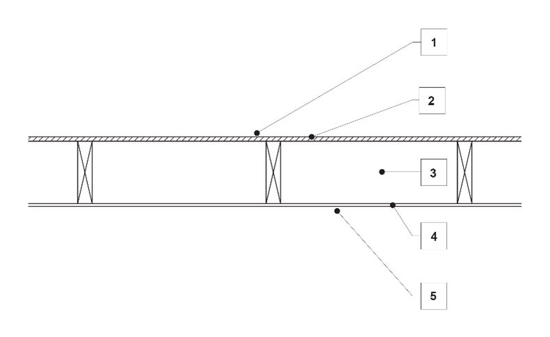
| Item no. | Description | R-Value | |
| Up | Down | ||
| 1. | Indoor air film (still air) | 0.11 | 0.16 |
| 2. | Particleboard flooring (19 mm, 640 kg/m3) | 0.15 | 0.15 |
| 3. | Floor airspace, 100 mm to 300 mm (non-reflective) | 0.15 | 0.22 |
| 4. | Plasterboard, gypsum (10 mm, 880 kg/m3) | 0.06 | 0.06 |
| 5. | Indoor air film (still air) | 0.11 | 0.16 |
| Total R-Value | 0.58 | 0.75 | |
Figure J4D7b: Timber, suspended ground floor, open subfloor
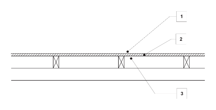
| Item no. | Description | R-Value | |
| Up | Down | ||
| 1. | Indoor air film(still air) | 0.11 | 0.16 |
| 2. | Particleboard flooring (19 mm, 640 kg/m3) | 0.15 | 0.15 |
| 3. | Outdoor air film(still air) | 0.04 | 0.04 |
| Total R-Value | 0.30 | 0.35 | |
Figure J4D7c: Solid concrete suspended slab
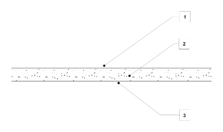
| Item no. | Description | R-Value | |
| Up | Down | ||
| 1. | Indoor air film(still air) | 0.11 | 0.16 |
| 2. | Solid concrete (150 mm, 2400kg/m3) | 0.10 | 0.10 |
| 3. | Outdoor air film(still air) | 0.04 | 0.04 |
| Total R-Value | 0.25 | 0.30 | |
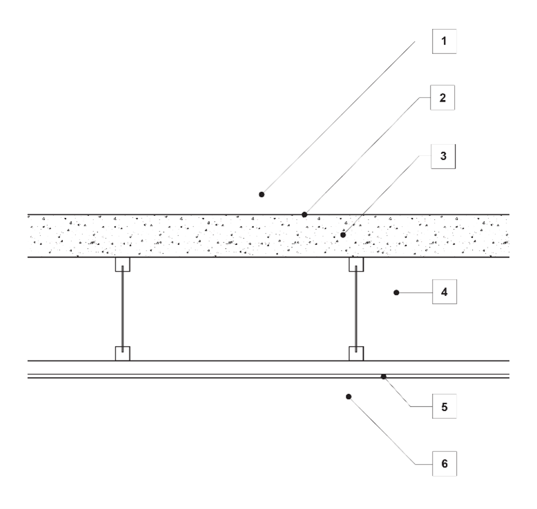
Figure J4D7d: 150 mm hollow-core concrete planks
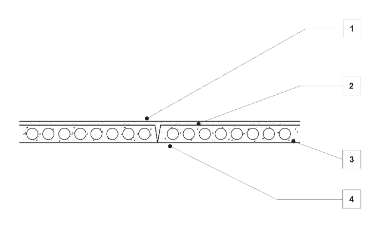
| Item no. | Description | R-Value | |
| Up | Down | ||
| 1. | Indoor air film(still air) | 0.11 | 0.16 |
| 2. | Concrete topping (60 mm, 2400 kg/m3) | 0.04 | 0.04 |
| 3. | Hollow-core concrete planks (150 mm, 1680 kg/m3,30% cores) | 0.14 | 0.14 |
| 4. | Outdoor air film(7 m/s) | 0.04 | 0.04 |
| Total R-Value | 0.33 | 0.38 | |
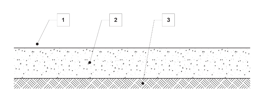
Figure J4D7e: 100 mm solid concrete slab-on-ground
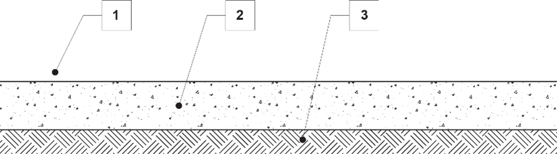
| Item no. | Description | R-Value | |
| Up | Down | ||
| 1. | Indoor air film(still air) | 0.11 | 0.16 |
| 2. | Solid concrete (100 mm, 2400kg/m3) | 0.07 | 0.07 |
| 3. | Ground thermal resistance | - | - |
| Total R-Value | 0.18 | 0.23 | |
Figure J4D7f: 150 mm solid concrete slab-on-ground
| Item no. | Description | R-Value | |
| Up | Down | ||
| 1. | Indoor air film(still air) | 0.11 | 0.16 |
| 2. | Solid concrete (150 mm, 2400kg/m3) | 0.10 | 0.10 |
| 3. | Ground thermal resistance | - | - |
| Total R-Value | 0.18 | 0.23 | |