NCC 2022 Volume One - Building Code of Australia Class 2 to 9 buildings
Search the National Construction Code editions
37
Specification 37 Calculation of U-Value and solar admittanceThis specification describes the methods of calculating the U-Value and solar admittance of a wall-glazing construction.
This Specification describes the two calculation methods for determining if wall-glazing construction complies with the U-Value and solar admittance requirements in J3D9, J4D3 and J4D6.
Two Deemed-to-Satisfy compliance pathways for both Total System U-Value and solar admittance are detailed in Specification 37:
In applying these methods, the Total System U-Value and Total System SHGC of glazing must account for the combined effect of the glass and frame. The measurement of these Total System U-Values and Total System SHGCs is specified in the Technical Protocols and Procedures Manual for Energy Rating of Fenestration Products of the Australian Fenestration Rating Council (AFRC).
Various assessors using AFRC procedures might refer to their published performance values by slightly different terms (including “U-factor” or “Uw” for Total System U-Value or “SHGC” for Total System SHGC). Such values can be used under Specification 37 provided they measure combined glass and frame performance according to AFRC requirements.
The presence of shading projections and devices will reduce the level of thermal performance that is required of glazing, as detailed in the calculation methods for solar admittance. However, to be effective, shading projections and devices must restrict a significant proportion of solar radiation.
External shading devices, such as shutters, blinds, vertical or horizontal building screens are required to be capable of restricting the amount of summer solar radiation that reaches the glazing by at least 80%. This is the sum of the amount of hour-by hour summer (December, January, February) solar radiation that does not reach the glazing as a percentage of what would have reached the glazing if the shading device was not fitted.
The 80% figure acknowledges that while a device may be capable of providing 100% shade during summer, some leakage of solar radiation may occur at the sides of the device. For example, although adjustable blinds are capable of providing 100% shade when they are fully closed or lowered, it is accepted that they may allow some summer solar radiation to reach the glazing at the sides of the blinds. Similarly, while a horizontal building screen may have slats which have been designed to provide 100% shade in summer, it is accepted that there may be some leakage of solar radiation at the sides of the slats.
A degree of judgement is required to determine whether the amount of summer solar radiation that reaches the glazing at the sides of a device exceeds that permitted.
Generally, a close fitting blind should sufficiently restrict the amount of summer solar radiation that reaches the glazing at the sides of the device.
A horizontal building screen that extends either side of the glazing by the same projection distance(P) should also restrict a sufficient amount of solar radiation at the sides of the slats.
Adjustables hading devices can only be recognised in the calculations if they are automatically operated. This is based on the premise that occupants are less likely to operate the devices as those in the best position to operate the devices are less inclined to do so because they are not paying the energy bills.
For complying with the shading requirement, note that the shading projection for walls is measured from the wall face whereas for glazing the projection is measured from the glass face.
Gutters can only be considered as providing shading if attached to a building projection such as a veranda, fixed canopy, eaves, shading hood, balcony or the like. On their own they are likely to be well above the head of the window and so not likely to produce any significant shading.
The figures below provide examples of typical insulation locations in various types of wall construction. The Total R-Value required is achieved by adding the material R-Value of the basic wall and the material R-Value of any additional insulation incorporated. The Total R-Value of the typical wall construction has been produced by adding together the material R- Values for outdoor air film, wall cladding, wall airspace, internal lining and internal air film.
Note it should not be assumed that these figures are representative of all construction scenarios. For example, the spacing of framing members, the number of windows or the specific type of frame could all effect the actual Total R-Value by creating thermal bridging between elements or by compressing insulation. If following a Deemed-to-Satisfy compliance pathway, Total R-Value must be calculated using the methods prescribed in AS/NZS4859.2 to properly account for these effects.
The most common forms of construction for low-rise buildings are represented. The Total R-Value of other forms of construction can be determined by adding the individual R-Values together.
For a material that is not listed as an item below, other than air, the R-Value may be determined by dividing the thickness of the item in metres by the thermal conductivity in W/m.K (typical values are described in Specification 36).
Reflective insulation that has just one reflective surface is considered to achieve the R-Values when used in conjunction with the Total R-Value of the common wall construction stated in the figure below. The actual R-Value added by reflective insulation should be determined for each product in accordance with the standards prescribed in the BCA, which take into consideration factors such as the number of adjacent airspaces, dimensions of the adjacent airspace, whether the space is ventilated and the presence of an anti-glare coating.
The width for any reflective airspaces adjacent to reflective insulation will not override other requirements such as minimum cavity requirements for masonry waterproofing.
Where a diagram shows reflective insulation or other insulation, these are indicative only. In some climates and using certain materials, neither may be necessary. In other cases, reflective insulation or other insulation may be provided separately or in combination to give the required R-Value.
A minimum thickness of 70 mm is stated for framing. In some cases, the frame thickness may need to be increased to avoid compressing the bulk insulation and thus reducing its R-Value.
| Density (kg/m3) | R-Value |
| 1430 | 0.16 |
| 1690 | 0.14 |
| 1950 | 0.12 |
| Density (kg/m3) | R-Value |
| 1430, 2.75 kg/brick | 0.20 |
| 1690, 3.25 kg/brick | 0.17 |
| 1950, 3.75 kg/brick | 0.14 |
| Size | R-Value |
| 110 mm | 0.12 |
| 190 mm | 0.20 |
Figure S37C1a: Masonry veneer – 25 mm to 50 mm cavity, 10 mm internal plaster on 90 mm stud frame
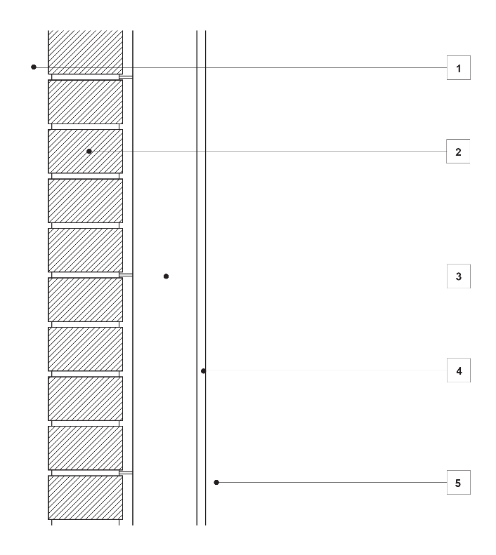
Figure Notes
Total R-Value = 0.48.
Figure S37C1b: Cavity masonry - 20 mm to 50 mm cavity, 10 mm internal plaster on battens or furring channels
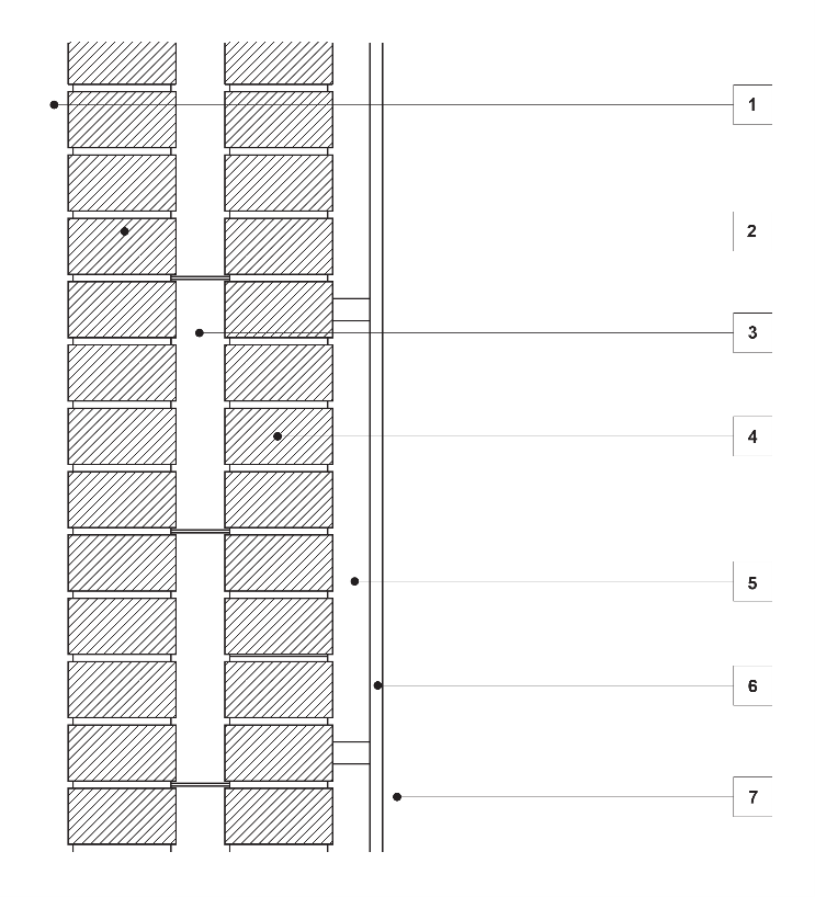
Figure Notes
Total R-Value =0.74.
Figure S37C1c: Dense weight hollow concrete block with internal plaster on battens or furring channels
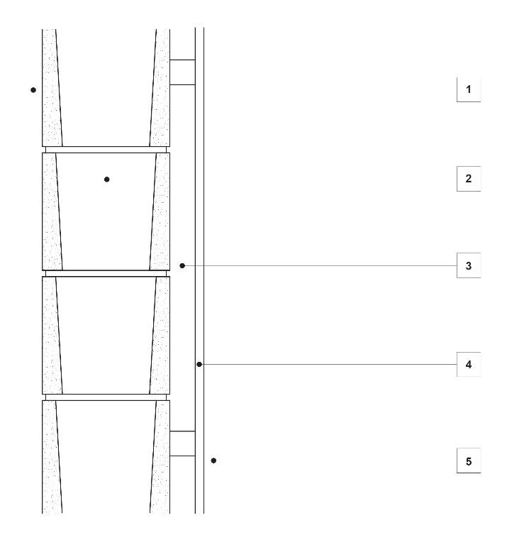
Figure Notes
Total R-Value =0.54.
Figure S37C1d: 125 mm solid reinforced concrete (dense weight) - 10 mm internal plaster on battens or furring channels
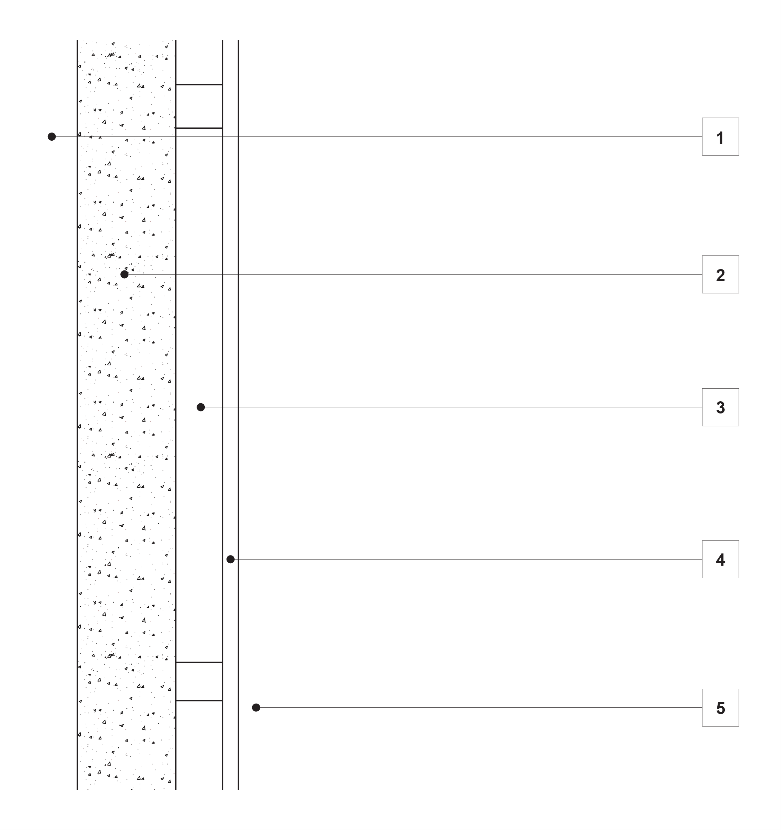
Figure Notes
Total R-Value = 0.48.
Figure S37C1e: Timber wall - external 6 mm cement sheet cladding, 90 mm stud frame, 10 mm plaster
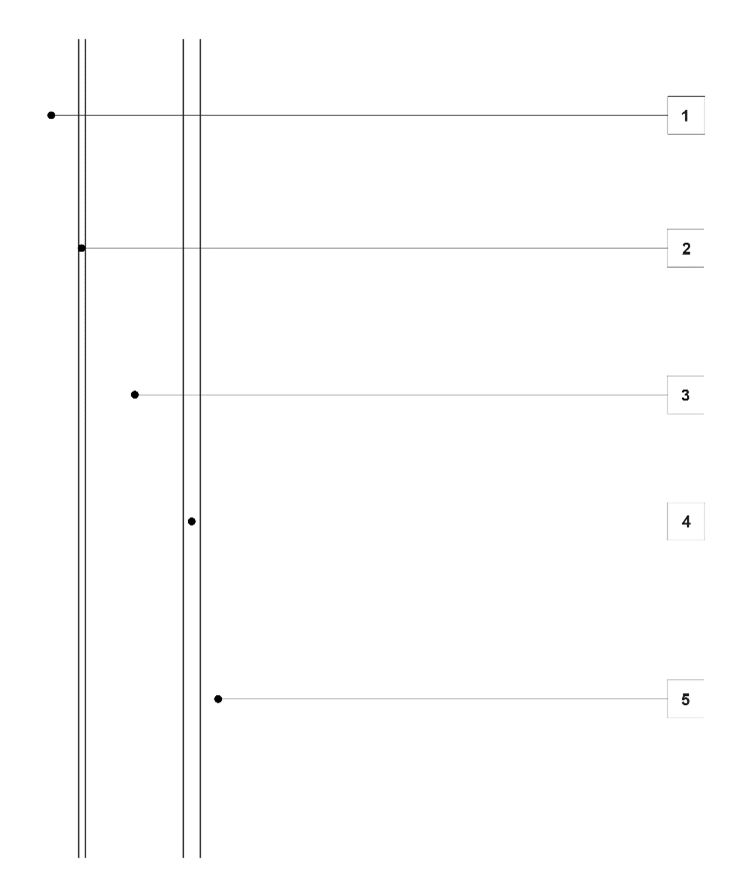
Figure Notes
Total R-Value = 0.42.
Figure S37C1f: 200 mm autoclaved aerated concrete block - 10 mm internal plaster on battens or furring channels
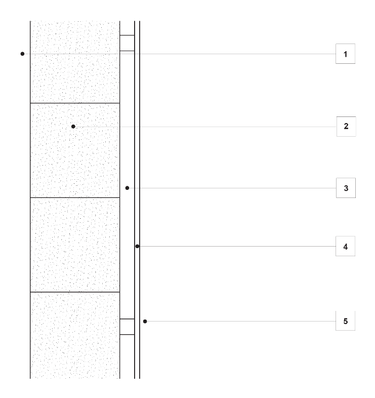
Figure Notes
Total R-Value = 2.39.
Figure S37C1g: 150 mm hollow-core concrete panels - 10 mm internal plaster on battens or furring chan- nels
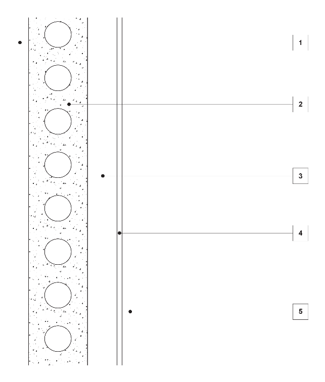
Figure Notes
Total R-Value = 0.53.
Figure S37C1h: Dense weight hollow concrete block with external 6 mm cement sheet cladding on bat- tens or furring channels
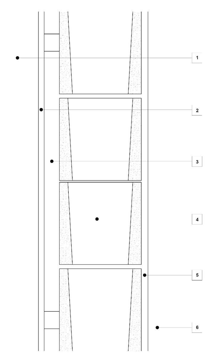
Figure Notes
Total R-Value = 0.12.
Figure S37C1i: Dense weight hollow concrete block with external 6 mm cement sheet cladding on bat- tens or furring channels
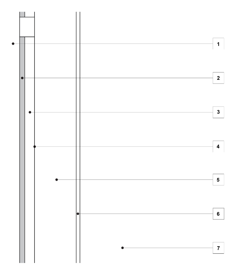
Figure Notes
Total R-Value = 0.57.
For determining the aspect of a wall-glazing construction—
| Aspect | Climate zone 1 | Climate zone 2 | Climate zone 3 | Climate zone 4 | Climate zone 5 | Climate zone 6 | Climate zone 7 | Climate zone 8 |
|---|---|---|---|---|---|---|---|---|
| Northern | 1.47 | 1.95 | 1.95 | 2.05 | 2.28 | 2.12 | 2.40 | 1.88 |
| Southern | 1.00 | 1.00 | 1.00 | 1.00 | 1.00 | 1.00 | 1.00 | 1.00 |
| Eastern | 1.39 | 1.58 | 1.63 | 1.72 | 1.72 | 1.62 | 1.84 | 1.92 |
| Western | 1.41 | 1.68 | 1.65 | 1.69 | 1.75 | 1.67 | 1.92 | 1.25 |
| Aspect | Climate zone 1 | Climate zone 2 | Climate zone 3 | Climate zone 4 | Climate zone 5 | Climate zone 6 | Climate zone 7 | Climate zone 8 |
|---|---|---|---|---|---|---|---|---|
| Northern | 1.42 | 1.77 | 1.72 | 1.55 | 1.88 | 1.52 | 1.60 | 1.24 |
| Southern | 1.00 | 1.00 | 1.00 | 1.00 | 1.00 | 1.00 | 1.00 | 1.00 |
| Eastern | 1.30 | 1.49 | 1.48 | 1.37 | 1.48 | 1.28 | 1.35 | 1.26 |
| Western | 1.37 | 1.54 | 1.50 | 1.36 | 1.52 | 1.33 | 1.40 | 1.05 |
For the purpose of calculating solar admittance, the shading multiplier is—
| G/H | P/H = 0 | P/H = 0.1 | P/H = 0.2 | P/H = 0.3 | P/H = 0.4 | P/H = 0.5 | P/H = 0.6 | P/H = 0.7 | P/H = 0.8 | P/H = 0.9 | P/H = 1 |
|---|---|---|---|---|---|---|---|---|---|---|---|
| 0 | 1.00 | 0.90 | 0.80 | 0.72 | 0.64 | 0.57 | 0.51 | 0.46 | 0.41 | 0.38 | 0.35 |
| 0.1 | 1.00 | 0.95 | 0.89 | 0.81 | 0.74 | 0.66 | 0.59 | 0.52 | 0.47 | 0.42 | 0.40 |
| 0.2 | 1.00 | 0.98 | 0.94 | 0.89 | 0.82 | 0.75 | 0.68 | 0.62 | 0.56 | 0.51 | 0.47 |
| 0.3 | 1.00 | 1.00 | 0.97 | 0.94 | 0.89 | 0.84 | 0.78 | 0.72 | 0.66 | 0.61 | 0.57 |
| 0.4 | 1.00 | 1.00 | 0.99 | 0.97 | 0.94 | 0.90 | 0.86 | 0.82 | 0.77 | 0.73 | 0.68 |
| 0.5 | 1.00 | 1.00 | 1.00 | 0.99 | 0.97 | 0.95 | 0.92 | 0.90 | 0.86 | 0.83 | 0.79 |
| G/H | P/H = 0 | P/H = 0.1 | P/H = 0.2 | P/H = 0.3 | P/H = 0.4 | P/H = 0.5 | P/H = 0.6 | P/H = 0.7 | P/H = 0.8 | P/H = 0.9 | P/H = 1 |
|---|---|---|---|---|---|---|---|---|---|---|---|
| 0 | 1.00 | 0.93 | 0.87 | 0.82 | 0.77 | 0.73 | 0.69 | 0.65 | 0.62 | 0.60 | 0.58 |
| 0.1 | 1.00 | 0.97 | 0.93 | 0.88 | 0.84 | 0.79 | 0.75 | 0.71 | 0.67 | 0.64 | 0.62 |
| 0.2 | 1.00 | 0.98 | 0.96 | 0.93 | 0.89 | 0.85 | 0.81 | 0.77 | 0.73 | 0.70 | 0.68 |
| 0.3 | 1.00 | 0.99 | 0.98 | 0.96 | 0.93 | 0.90 | 0.87 | 0.83 | 0.80 | 0.77 | 0.74 |
| 0.4 | 1.00 | 1.00 | 0.99 | 0.98 | 0.96 | 0.94 | 0.91 | 0.89 | 0.86 | 0.84 | 0.81 |
| 0.5 | 1.00 | 1.00 | 0.99 | 0.99 | 0.98 | 0.96 | 0.95 | 0.93 | 0.91 | 0.90 | 0.88 |
