NCC 2022 Volume One - Building Code of Australia Class 2 to 9 buildings
Classification
Building class 1a Building class 1b Building class 2 Building class 3 Building class 4 Building class 5 Building class 6 Building class 7a Building class 7b Building class 8 Building class 9a Building class 9b Building class 9c Building class 10a Building class 10b Building class 10c

Filter

Classification
Building class 1a Building class 1b Building class 2 Building class 3 Building class 4 Building class 5 Building class 6 Building class 7a Building class 7b Building class 8 Building class 9a Building class 9b Building class 9c Building class 10a Building class 10b Building class 10c

B1

Part B1 Structural provisions

Part B1 Structural provisions

Introduction to this Part

This Part focuses on safeguarding people from injury caused by structural failure, loss of amenity caused by structural behaviour (deflections, creep, vibration, settlement and the like), protection of other property from physical damage caused by structural failure and safeguarding people from injury that may be caused by failure of, or impact with, glazing.

Objectives

The Objective of this Part is to—

  1. safeguard people from injury caused by structural failure; and
  2. safeguard people from loss of amenity caused by structural behaviour; and
  3. protect other property from physical damage caused by structural failure; and
  4. safeguard people from injury that may be caused by failure of, or impact with, glazing.


The Objective is based on the belief that people should not be subject to risk of injury from a building suffering structural failure—B1O1(a). Nor should there be any amenity loss caused by structural behaviour—B1O1(b). Additionally, other property should not be at risk of physical damage caused by structural failure—B1O1(c) and people should be safeguarded from injury due to failure or impact with glazing—B1O1(d).
The term “structural behaviour” as used in B1O1(b) can describe deflections, creep, vibration, settlement and the like. Problems with structural behaviour fall short of actual structural failure.

Example
A building could have excessive deflection of a window lintel which causes the glass to shatter. This could interfere with the building’s use without causing it to collapse.

“Loss of amenity” refers to the loss of a person’s ability to use a building in the manner intended.

Example
Structural deflections could cause a building’s doors to stick, and thus detract from a person’s ability to move about the building.

Functional Statements

A building or structure is to withstand the combination of loads and other actions to which it may be reasonably subjected.

(1) Glazing is to be installed in a building to avoid undue risk of injury to people.

(2) Glazing in a building should not cause injury to people due to its failure or people impacting with it because they did not see it.

Performance Requirements

(1) By resisting the actions to which it may reasonably be expected to be subjected, a building or structure, during construction and use, with appropriate degrees of reliability, must—

  1. perform adequately under all reasonably expected design actions; and
  2. withstand extreme or frequently repeated design actions; and
  3. be designed to sustain local damage, with the structural system as a whole remaining stable and not being damaged to an extent disproportionate to the original local damage; and
  4. avoid causing damage to other properties.

(2) The actions to be considered to satisfy (1) include but are not limited to—

  1. permanent actions (dead loads) including, for a Class 7b building, an additional notional permanent roof load of not less than 0.15 kPa to support the addition of solar photovoltaic panels; and
  2. imposed actions (live loads arising from occupancy and use); and
  3. wind action; and
  4. earthquake action; and
  5. snow action; and
  6. liquid pressure action; and
  7. ground water action; and
  8. rainwater action (including ponding action); and
  9. earth pressure action; and
  10. differential movement; and
  11. time dependent effects (including creep and shrinkage); and
  12. thermal effects; and
  13. ground movement caused by—
    1. swelling, shrinkage or freezing of the subsoil; and
    2. landslip or subsidence; and
    3. siteworks associated with the building or structure; and
  14. construction activity actions; and
  15. termite actions.

Exemptions

The requirement for an additional notional permanent roof load to support photovoltaic panels in B1P1(2)(a) does not apply to a Class 7b building—

  1. where 100% of the roof area is shaded for more than 70% of daylight hours; or
  2. with a roof area of not more than 55 m2; or
  3. where more than 50% of the roof area is used as a terrace, carpark, roof garden, roof light or the like.

Notes

The requirement in B1P1(2)(a) to consider, for a Class 7b building, an additional notional permanent roof load of not less than 0.15 kPa to support the addition of solar photovoltaic panels does not take effect until 1 October 2023.


B1P1 consists of two parts:
•    performance attributes that a building is required to have; and
•    a list of actions to be considered in association with these attributes.


Performance attributes
B1P1(1) uses the term “with appropriate degrees of reliability” which can be judged with due regard to the possible consequences of failure and the expense, level of effort and procedures necessary to reduce the risk of failure. The measures that can be taken to achieve the appropriate degree of reliability include:
•    choice of a structural system, proper design and analysis;
•    implementation of a quality policy;
•    design for durability and maintenance; and
•    protective measures.


Degrees of reliability of structural elements can be quantified in terms of probabilities of failure with the use of probabilistic models for actions and resistances.


B1P1(1)(a) is concerned with the serviceability limit states of buildings in terms of local damage, deformation and vibration. Expected actions are actions with high probabilities of occurrence. The acceptable level of serviceability is subjective. The design for serviceability depends to a large extent on professional judgement. The risk of serviceability failure is, historically, of the order of 10-1 to 10-2.


B1P1(1)(b) is concerned with the ultimate limit states of buildings in terms of strength and stability. Extreme actions are actions with low probability of occurrence. Repeated actions are actions, with high frequencies of occurrence in a given time period, that may cause fatigue or other cumulative failures. The notional probability of failure of structural elements is of the order of 10-3 to 10-4 for a 50 year reference period. The probability of structural failure is historically of the order of 10-6 per year.


B1P1(1)(c) is concerned with consequences of unspecified actions and is often referred to as “structural robustness”. It includes, but is not limited to, progressive collapse. Ways to improve structural robustness include providing redundancies, minimum resistances, protective measures, etc.


B1P1(1)(d) is concerned with damage to other properties, which may be caused by reasons other than structural if B1P1(1)(a) to (c) are met.


List of actions
B1P1(2) lists actions to which a building “may reasonably be subjected”. All possible actions cannot be listed. “Engineering judgement” may need to be used to determine all likely actions and in accessing the likely effects of those actions.

Example
Buildings and structures should be able to withstand the effects of wind, rain or snow. However, they would not be expected to withstand the impact of a crashing aeroplane.

B1P1(2)(n) uses the defined term “construction activity actions”. The term only refers to construction activities that may have an effect on the final design such as stacking or propping. The safety of the building during construction is normally controlled by occupational health and safety authorities.

The structural resistance of materials and forms of construction must be determined using five percentile characteristic material properties with appropriate allowance for—

  1. known construction activities; and
  2. type of material; and
  3. characteristics of the site; and
  4. the degree of accuracy inherent in the methods used to assess the structural behaviour; and
  5. action effects arising from the differential settlement of foundations, and from restrained dimensional changes due to temperature, moisture, shrinkage, creep and similar effects.


B1P2 states the principles for the determination of the structural resistance of materials and forms of construction.

It should be noted that the construction activities referred to in B1P2(a) may be more than those contained in the defined term of “construction activity actions”. For example, welding of structural steel might cause distortion or change the characteristics of the steel, and hence need to be accounted for. For this reason, the defined term has not been used in B1P2(a).

Glass installations that are at risk of being subjected to human impact must have glazing that—

  1. if broken on impact, will break in a way that is not likely to cause injury to people; and
  2. resists a reasonably foreseeable human impact without breaking; and
  3. is protected or marked in a way that will reduce the likelihood of human impact.


Glazing in a building is not always readily visible to all people. It is therefore important to avoid human impact where possible. This may not always be possible. B1P3 therefore contains three parts:
•    if glazing is broken due to human impact, it must fail so that small pieces will not cause injury to people (B1P3(a));
•    if human impact could occur, the glazing should be of a strength to resist that impact without breaking (B1P3(b)); and
•    to make it more visible, glazing should be marked with a motif or the like (B1P3(c)).

NCC Title
Buildings in flood areas
NCC State
SA
NCC Variation Type
Deletion
NCC SPTC Current
Buildings in flood areas
NCC Title
Buildings in flood areas
NCC State
QLD
NCC Variation Type
Deletion
NCC SPTC Current
Buildings in flood areas
NCC Notice
Building work in designated flood areas is regulated by the Building Act 1975 and the Queensland Development Code 3.5 - Construction of buildings in flood hazard areas

(1) A building in a flood hazard area, must be designed and constructed, to the degree necessary, to resist flotation, collapse or significant permanent movement resulting from the action of hydrostatic, hydrodynamic, erosion and scour, wind and other actions during the defined flood event.

(2) The actions and requirements to be considered to satisfy (1) include but are not limited to—

  1. flood actions; and
  2. elevation requirements; and
  3. foundation and footing requirements; and
  4. requirements for enclosures below the flood hazard level; and
  5. requirements for structural connections; and
  6. material requirements; and
  7. requirements for utilities; and
  8. requirements for occupant egress.

Applications

B1P4 only applies to—

  1. a Class 2 or 3 building or a Class 4 part of a building; and
  2. a Class 9a health-care building; and
  3. a Class 9c building.


B1P4 only applies to buildings in which people are likely to sleep that are located in a flood hazard area, i.e. a Class 2 or 3 building or a Class 4 part of a building, a Class 9a health-care building or a Class 9c building. A flood hazard area is determined by the appropriate authority (usually the relevant local government) as an area to be affected by flood. The determination is usually via a planning instrument. It is important to note that the NCC provision does not override a provision in a planning instrument which may restrict development in a flood hazard area.

B1P4 states the principles for the design and construction of the specified buildings in a flood event. The principles include preventing—
•    buildings suffering structural damage or collapse due to hydrostatic effect (pressure of still water), hydrodynamic effect (force of moving water) or debris impact; and
•    buildings from being lifted off foundations or footings due to buoyancy effect; and
•    foundations and footings being affected by scour or erosion caused by moving water; and
•    degradation of structural materials as a result of being immersed in water.

Verification Methods

(1) This Verification Method is applicable to components with a resistance coefficient of variation of at least 10% and not more than 40%.

(2) Where a component has a calculated resistance coefficient of variation of less than 10%, then a minimum value of 10% must be used.

(3) Compliance with B1P1 and B1P2 is verified for the design of a structural component for strength where—

  1. the capacity reduction factor
    ϕMathType@MTEF@5@5@+= feaahqart1ev3aqatCvAUfeBSjuyZL2yd9gzLbvyNv2CaerbuLwBLn hiov2DGi1BTfMBaeXatLxBI9gBaerbd9wDYLwzYbItLDharqqtubsr 4rNCHbGeaGqiVu0Je9sqqrpepC0xbbL8F4rqqrFfpeea0xe9Lq=Jc9 vqaqpepm0xbba9pwe9Q8fs0=yqaqpepae9pg0FirpepeKkFr0xfr=x fr=xb9adbaqaaeGaciGaaiaabeqaamaabaabaaGcbaGaeqy1dygaaa@37BC@  
    satisfies
    ϕAverage(ϕG,ϕQ,ϕW,...)MathType@MTEF@5@5@+= feaahqart1ev3aqatCvAUfeBSjuyZL2yd9gzLbvyNv2CaerbuLwBLn hiov2DGi1BTfMBaeXatLxBI9gBaerbd9wDYLwzYbItLDharqqtubsr 4rNCHbGeaGqiVu0Je9sqqrpepC0xbbL8F4rqqrFfpeea0xe9Lq=Jc9 vqaqpepm0xbba9pwe9Q8fs0=yqaqpepae9pg0FirpepeKkFr0xfr=x fr=xb9adbaqaaeGaciGaaiaabeqaamaabaabaaGcbaGaeqy1dyMaey izImQaamyqaiaadAhacaWGLbGaamOCaiaadggacaWGNbGaamyzaiaa cIcacqaHvpGzdaWgaaWcbaGaam4raaqabaGccaGGSaGaeqy1dy2aaS baaSqaaiaadgfaaeqaaOGaaiilaiabew9aMnaaBaaaleaacaWGxbaa beaakiaacYcacaGGUaGaaiOlaiaac6cacaGGPaaaaa@4DC6@  
    , where
    ϕG,ϕQ,ϕW,...MathType@MTEF@5@5@+= feaahqart1ev3aqatCvAUfeBSjuyZL2yd9gzLbvyNv2CaerbuLwBLn hiov2DGi1BTfMBaeXatLxBI9gBaerbd9wDYLwzYbItLDharqqtubsr 4rNCHbGeaGqiVu0Je9sqqrpepC0xbbL8F4rqqrFfpeea0xe9Lq=Jc9 vqaqpepm0xbba9pwe9Q8fs0=yqaqpepae9pg0FirpepeKkFr0xfr=x fr=xb9adbaqaaeGaciGaaiaabeqaamaabaabaaGcbaGaeqy1dy2aaS baaSqaaiaadEeaaeqaaOGaaiilaiabew9aMnaaBaaaleaacaWGrbaa beaakiaacYcacqaHvpGzdaWgaaWcbaGaam4vaaqabaGccaGGSaGaai Olaiaac6cacaGGUaaaaa@4292@  
    are capacity reduction factors for all relevant actions and must contain at least permanent (G), imposed (Q) and wind (W) actions; and
  2. the capacity reduction factors
    ϕG,ϕQ,ϕW,...MathType@MTEF@5@5@+= feaahqart1ev3aqatCvAUfeBSjuyZL2yd9gzLbvyNv2CaerbuLwBLn hiov2DGi1BTfMBaeXatLxBI9gBaerbd9wDYLwzYbItLDharqqtubsr 4rNCHbGeaGqiVu0Je9sqqrpepC0xbbL8F4rqqrFfpeea0xe9Lq=Jc9 vqaqpepm0xbba9pwe9Q8fs0=yqaqpepae9pg0FirpepeKkFr0xfr=x fr=xb9adbaqaaeGaciGaaiaabeqaamaabaabaaGcbaGaeqy1dy2aaS baaSqaaiaadEeaaeqaaOGaaiilaiabew9aMnaaBaaaleaacaWGrbaa beaakiaacYcacqaHvpGzdaWgaaWcbaGaam4vaaqabaGccaGGSaGaai Olaiaac6cacaGGUaaaaa@4292@  
    are calculated for target reliability indices for permanent action
    βTGMathType@MTEF@5@5@+= feaahqart1ev3aqatCvAUfeBSjuyZL2yd9gzLbvyNv2CaerbuLwBLn hiov2DGi1BTfMBaeXatLxBI9gBaerbd9wDYLwzYbItLDharqqtubsr 4rNCHbGeaGqiVu0Je9sqqrpepC0xbbL8F4rqqrFfpeea0xe9Lq=Jc9 vqaqpepm0xbba9pwe9Q8fs0=yqaqpepae9pg0FirpepeKkFr0xfr=x fr=xb9adbaqaaeGaciGaaiaabeqaamaabaabaaGcbaGaeqOSdi2aaS baaSqaaiaadsfacaWGhbaabeaaaaa@3966@  
    , for imposed action
    βTQMathType@MTEF@5@5@+= feaahqart1ev3aqatCvAUfeBSjuyZL2yd9gzLbvyNv2CaerbuLwBLn hiov2DGi1BTfMBaeXatLxBI9gBaerbd9wDYLwzYbItLDharqqtubsr 4rNCHbGeaGqiVu0Je9sqqrpepC0xbbL8F4rqqrFfpeea0xe9Lq=Jc9 vqaqpepm0xbba9pwe9Q8fs0=yqaqpepae9pg0FirpepeKkFr0xfr=x fr=xb9adbaqaaeGaciGaaiaabeqaamaabaabaaGcbaGaeqOSdi2aaS baaSqaaiaadsfacaWGrbaabeaaaaa@3970@  
    , for wind action
    βTWMathType@MTEF@5@5@+= feaahqart1ev3aqatCvAUfeBSjuyZL2yd9gzLbvyNv2CaerbuLwBLn hiov2DGi1BTfMBaeXatLxBI9gBaerbd9wDYLwzYbItLDharqqtubsr 4rNCHbGeaGqiVu0Je9sqqrpepC0xbbL8F4rqqrFfpeea0xe9Lq=Jc9 vqaqpepm0xbba9pwe9Q8fs0=yqaqpepae9pg0FirpepeKkFr0xfr=x fr=xb9adbaqaaeGaciGaaiaabeqaamaabaabaaGcbaGaeqOSdi2aaS baaSqaaiaadsfacaWGxbaabeaaaaa@3976@  
    ,… in accordance with the equation:
    β=lnR¯S¯CSCR/ln(CR.CS)MathType@MTEF@5@5@+= feaahqart1ev3aqatCvAUfeBSjuyZL2yd9gzLbvyNv2CaerbuLwBLn hiov2DGi1BTfMBaeXatLxBI9gBaerbd9wDYLwzYbItLDharqqtubsr 4rNCHbGeaGqiVu0Je9sqqrpepC0xbbL8F4rqqrFfpeea0xe9Lq=Jc9 vqaqpepm0xbba9pwe9Q8fs0=yqaqpepae9pg0FirpepeKkFr0xfr=x fr=xb9adbaqaaeGaciGaaiaabeqaamaabaabaaGcbaGaeqOSdiMaey ypa0JaciiBaiaac6gadaWadaqaamaabmaabaWaaSaaaeaadaqdaaqa aiaadkfaaaaabaWaa0aaaeaacaWGtbaaaaaaaiaawIcacaGLPaaada GcaaqaamaalaaabaGaam4qamaaBaaaleaacaWGtbaabeaaaOqaaiaa doeadaWgaaWcbaGaamOuaaqabaaaaaqabaaakiaawUfacaGLDbaaca GGVaWaaOaaaeaaciGGSbGaaiOBaiaacIcacaWGdbWaaSbaaSqaaiaa dkfaaeqaaOGaaiOlaiaadoeadaWgaaWcbaGaam4uaaqabaGccaGGPa aaleqaaaaa@4C0E@  
    , where—
    1. R¯S¯=γϕS¯SNR¯RNMathType@MTEF@5@5@+= feaahqart1ev3aqatCvAUfeBSjuyZL2yd9gzLbvyNv2CaerbuLwBLn hiov2DGi1BTfMBaeXatLxBI9gBaerbd9wDYLwzYbItLDharqqtubsr 4rNCHbGeaGqiVu0Je9sqqrpepC0xbbL8F4rqqrFfpeea0xe9Lq=Jc9 vqaqpepm0xbba9pwe9Q8fs0=yqaqpepae9pg0FirpepeKkFr0xfr=x fr=xb9adbaqaaeGaciGaaiaabeqaamaabaabaaGcbaWaaeWaaeaada WcaaqaamaanaaabaGaamOuaaaaaeaadaqdaaqaaiaadofaaaaaaaGa ayjkaiaawMcaaiabg2da9maalaaabaWaaeWaaeaadaWcaaqaaiabeo 7aNbqaaiabew9aMbaaaiaawIcacaGLPaaaaeaadaqadaqaamaalaaa baWaa0aaaeaacaWGtbaaaaqaaiaadofadaWgaaWcbaGaamOtaaqaba aaaaGccaGLOaGaayzkaaaaamaabmaabaWaaSaaaeaadaqdaaqaaiaa dkfaaaaabaGaamOuamaaBaaaleaacaWGobaabeaaaaaakiaawIcaca GLPaaaaaa@4840@  
      ; and
    2. CR=1+VR2CS=1+VS2 MathType@MTEF@5@5@+= feaahqart1ev3aqatCvAUfeBSjuyZL2yd9gzLbvyNv2CaerbuLwBLn hiov2DGi1BTfMBaeXatLxBI9gBaerbd9wDYLwzYbItLDharqqtubsr 4rNCHbGeaGqiVu0Je9sqqrpepC0xbbL8F4rqqrFfpeea0xe9Lq=Jc9 vqaqpepm0xbba9pwe9Q8fs0=yqaqpepae9pg0FirpepeKkFr0xfr=x fr=xb9adbaqaaeGaciGaaiaabeqaamaabaabaaGceaqabeaacaWGdb WaaSbaaSqaaiaadkfaaeqaaOGaeyypa0JaaGymaiabgUcaRiaadAfa daqhaaWcbaGaamOuaaqaaiaaikdaaaaakeaacaWGdbWaaSbaaSqaai aadofaaeqaaOGaeyypa0JaaGymaiabgUcaRiaadAfadaqhaaWcbaGa am4uaaqaaiaaikdaaaaaaaa@442D@  
      , where—
      1. R¯RNMathType@MTEF@5@5@+= feaahqart1ev3aqatCvAUfeBSjuyZL2yd9gzLbvyNv2CaerbuLwBLn hiov2DGi1BTfMBaeXatLxBI9gBaerbd9wDYLwzYbItLDharqqtubsr 4rNCHbGeaGqiVu0Je9sqqrpepC0xbbL8F4rqqrFfpeea0xe9Lq=Jc9 vqaqpepm0xbba9pwe9Q8fs0=yqaqpepae9pg0FirpepeKkFr0xfr=x fr=xb9adbaqaaeGaciGaaiaabeqaamaabaabaaGcbaWaaSaaaeaada qdaaqaaiaadkfaaaaabaGaamOuamaaBaaaleaacaWGobaabeaaaaaa aa@38C2@  
        = ratio of mean resistance to nominal; and
      2. S¯SNMathType@MTEF@5@5@+= feaahqart1ev3aqatCvAUfeBSjuyZL2yd9gzLbvyNv2CaerbuLwBLn hiov2DGi1BTfMBaeXatLxBI9gBaerbd9wDYLwzYbItLDharqqtubsr 4rNCHbGeaGqiVu0Je9sqqrpepC0xbbL8F4rqqrFfpeea0xe9Lq=Jc9 vqaqpepm0xbba9pwe9Q8fs0=yqaqpepae9pg0FirpepeKkFr0xfr=x fr=xb9adbaqaaeGaciGaaiaabeqaamaabaabaaGcbaWaaSaaaeaada qdaaqaaiaadofaaaaabaGaam4uamaaBaaaleaacaWGobaabeaaaaaa aa@38C4@  
        = ratio of mean action to nominal; and
      3. CSMathType@MTEF@5@5@+= feaahqart1ev3aqatCvAUfeBSjuyZL2yd9gzLbvyNv2CaerbuLwBLn hiov2DGi1BTfMBaeXatLxBI9gBaerbd9wDYLwzYbItLDharqqtubsr 4rNCHbGeaGqiVu0Je9sqqrpepC0xbbL8F4rqqrFfpeea0xe9Lq=Jc9 vqaqpepm0xbba9pwe9Q8fs0=yqaqpepae9pg0FirpepeKkFr0xfr=x fr=xb9adbaqaaeGaciGaaiaabeqaamaabaabaaGcbaGaam4qamaaBa aaleaacaWGtbaabeaaaaa@37C0@  
        = correction factor for action; and
      4. CRMathType@MTEF@5@5@+= feaahqart1ev3aqatCvAUfeBSjuyZL2yd9gzLbvyNv2CaerbuLwBLn hiov2DGi1BTfMBaeXatLxBI9gBaerbd9wDYLwzYbItLDharqqtubsr 4rNCHbGeaGqiVu0Je9sqqrpepC0xbbL8F4rqqrFfpeea0xe9Lq=Jc9 vqaqpepm0xbba9pwe9Q8fs0=yqaqpepae9pg0FirpepeKkFr0xfr=x fr=xb9adbaqaaeGaciGaaiaabeqaamaabaabaaGcbaGaam4qamaaBa aaleaacaWGsbaabeaaaaa@37BF@  
        = correction factor for resistance; and
      5. VSMathType@MTEF@5@5@+= feaahqart1ev3aqatCvAUfeBSjuyZL2yd9gzLbvyNv2CaerbuLwBLn hiov2DGi1BTfMBaeXatLxBI9gBaerbd9wDYLwzYbItLDharqqtubsr 4rNCHbGeaGqiVu0Je9sqqrpepC0xbbL8F4rqqrFfpeea0xe9Lq=Jc9 vqaqpepm0xbba9pwe9Q8fs0=yqaqpepae9pg0FirpepeKkFr0xfr=x fr=xb9adbaqaaeGaciGaaiaabeqaamaabaabaaGcbaGaamOvamaaBa aaleaacaWGtbaabeaaaaa@37D3@  
        = coefficient of variation of the appropriate action as given in Table B1V1a; and
      6. VRMathType@MTEF@5@5@+= feaahqart1ev3aqatCvAUfeBSjuyZL2yd9gzLbvyNv2CaerbuLwBLn hiov2DGi1BTfMBaeXatLxBI9gBaerbd9wDYLwzYbItLDharqqtubsr 4rNCHbGeaGqiVu0Je9sqqrpepC0xbbL8F4rqqrFfpeea0xe9Lq=Jc9 vqaqpepm0xbba9pwe9Q8fs0=yqaqpepae9pg0FirpepeKkFr0xfr=x fr=xb9adbaqaaeGaciGaaiaabeqaamaabaabaaGcbaGaamOvamaaBa aaleaacaWGsbaabeaaaaa@37D2@  
        = coefficient of variation of the resistance; and
      7. γMathType@MTEF@5@5@+= feaahqart1ev3aqatCvAUfeBSjuyZL2yd9gzLbvyNv2CaerbuLwBLn hiov2DGi1BTfMBaeXatLxBI9gBaerbd9wDYLwzYbItLDharqqtubsr 4rNCHbGeaGqiVu0Je9sqqrpepC0xbbL8F4rqqrFfpeea0xe9Lq=Jc9 vqaqpepm0xbba9pwe9Q8fs0=yqaqpepae9pg0FirpepeKkFr0xfr=x fr=xb9adbaqaaeGaciGaaiaabeqaamaabaabaaGcbaGaeq4SdCgaaa@379B@  
        = appropriate load factor for the action as given in AS/NZS 1170.0; and
      8. ϕMathType@MTEF@5@5@+= feaahqart1ev3aqatCvAUfeBSjuyZL2yd9gzLbvyNv2CaerbuLwBLn hiov2DGi1BTfMBaeXatLxBI9gBaerbd9wDYLwzYbItLDharqqtubsr 4rNCHbGeaGqiVu0Je9sqqrpepC0xbbL8F4rqqrFfpeea0xe9Lq=Jc9 vqaqpepm0xbba9pwe9Q8fs0=yqaqpepae9pg0FirpepeKkFr0xfr=x fr=xb9adbaqaaeGaciGaaiaabeqaamaabaabaaGcbaGaeqy1dygaaa@37BC@  
        = capacity factor for the appropriate action; and
  3. the annual target reliability indices
    βTG,βTQ,βTW,...MathType@MTEF@5@5@+= feaahqart1ev3aqatCvAUfeBSjuyZL2yd9gzLbvyNv2CaerbuLwBLn hiov2DGi1BTfMBaeXatLxBI9gBaerbd9wDYLwzYbItLDharqqtubsr 4rNCHbGeaGqiVu0Je9sqqrpepC0xbbL8F4rqqrFfpeea0xe9Lq=Jc9 vqaqpepm0xbba9pwe9Q8fs0=yqaqpepae9pg0FirpepeKkFr0xfr=x fr=xb9adbaqaaeGaciGaaiaabeqaamaabaabaaGcbaGaeqOSdi2aaS baaSqaaiaadsfacaWGhbaabeaakiaacYcacqaHYoGydaWgaaWcbaGa amivaiaadgfaaeqaaOGaaiilaiabek7aInaaBaaaleaacaWGubGaam 4vaaqabaGccaGGSaGaaiOlaiaac6cacaGGUaaaaa@44A8@  
    are established as follows:
    1. For situations where it is appropriate to compare an equivalent Deemed-to-Satisfy product, a resistance model must be established for the equivalent Deemed-to-Satisfy product and
      βTG,βTQ,βTW,...MathType@MTEF@5@5@+= feaahqart1ev3aqatCvAUfeBSjuyZL2yd9gzLbvyNv2CaerbuLwBLn hiov2DGi1BTfMBaeXatLxBI9gBaerbd9wDYLwzYbItLDharqqtubsr 4rNCHbGeaGqiVu0Je9sqqrpepC0xbbL8F4rqqrFfpeea0xe9Lq=Jc9 vqaqpepm0xbba9pwe9Q8fs0=yqaqpepae9pg0FirpepeKkFr0xfr=x fr=xb9adbaqaaeGaciGaaiaabeqaamaabaabaaGcbaGaeqOSdi2aaS baaSqaaiaadsfacaWGhbaabeaakiaacYcacqaHYoGydaWgaaWcbaGa amivaiaadgfaaeqaaOGaaiilaiabek7aInaaBaaaleaacaWGubGaam 4vaaqabaGccaGGSaGaaiOlaiaac6cacaGGUaaaaa@44A8@  
      must be calculated for the equivalent Deemed-to-Satisfy product in accordance with the equation given at (b).
    2. The target reliability indices
      βTG,βTQ,βTW,...MathType@MTEF@5@5@+= feaahqart1ev3aqatCvAUfeBSjuyZL2yd9gzLbvyNv2CaerbuLwBLn hiov2DGi1BTfMBaeXatLxBI9gBaerbd9wDYLwzYbItLDharqqtubsr 4rNCHbGeaGqiVu0Je9sqqrpepC0xbbL8F4rqqrFfpeea0xe9Lq=Jc9 vqaqpepm0xbba9pwe9Q8fs0=yqaqpepae9pg0FirpepeKkFr0xfr=x fr=xb9adbaqaaeGaciGaaiaabeqaamaabaabaaGcbaGaeqOSdi2aaS baaSqaaiaadsfacaWGhbaabeaakiaacYcacqaHYoGydaWgaaWcbaGa amivaiaadgfaaeqaaOGaaiilaiabek7aInaaBaaaleaacaWGubGaam 4vaaqabaGccaGGSaGaaiOlaiaac6cacaGGUaaaaa@44A8@  
      thus established, must be not less than those given in Table B1V1b minus 0.5.
    3. For situations where it is not appropriate to compare with an equivalent Deemed-to-Satisfy product, the target reliability index
      βMathType@MTEF@5@5@+= feaahqart1ev3aqatCvAUfeBSjuyZL2yd9gzLbvyNv2CaerbuLwBLn hiov2DGi1BTfMBaeXatLxBI9gBaerbd9wDYLwzYbItLDharqqtubsr 4rNCHbGeaGqiVu0Je9sqqrpepC0xbbL8F4rqqrFfpeea0xe9Lq=Jc9 vqaqpepm0xbba9pwe9Q8fs0=yqaqpepae9pg0FirpepeKkFr0xfr=x fr=xb9adbaqaaeGaciGaaiaabeqaamaabaabaaGcbaGaeqOSdigaaa@3795@  
      must be as given in Table B1V1b.

(4) The resistance model for the component must be established by taking into account variability due to material properties, fabrication and construction processes and structural modelling.

Table B1V1a Annual action models
Design action Ratio of mean action to nominal Coefficient of variation of the action
Permanent action
(γG=1.35)MathType@MTEF@5@5@+= feaahqart1ev3aqatCvAUfeBSjuyZL2yd9gzLbvyNv2CaerbuLwBLn hiov2DGi1BTfMBaeXatLxBI9gBaerbd9wDYLwzYbItLDharqqtubsr 4rNCHbGeaGqiVu0Je9sqqrpepC0xbbL8F4rqqrFfpeea0xe9Lq=Jc9 vqaqpepm0xbba9pwe9Q8fs0=yqaqpepae9pg0FirpepeKkFr0xfr=x fr=xb9adbaqaaeGaciGaaiaabeqaamaabaabaaGcbaGaaiikaiabeo 7aNnaaBaaaleaacaWGhbaabeaakiabg2da9iaaigdacaGGUaGaaG4m aiaaiwdacaGGPaaaaa@3DE5@
(G¯/GN)=1.00MathType@MTEF@5@5@+= feaahqart1ev3aqatCvAUfeBSjuyZL2yd9gzLbvyNv2CaerbuLwBLn hiov2DGi1BTfMBaeXatLxBI9gBaerbd9wDYLwzYbItLDharqqtubsr 4rNCHbGeaGqiVu0Je9sqqrpepC0xbbL8F4rqqrFfpeea0xe9Lq=Jc9 vqaqpepm0xbba9pwe9Q8fs0=yqaqpepae9pg0FirpepeKkFr0xfr=x fr=xb9adbaqaaeGaciGaaiaabeqaamaabaabaaGcbaGaaiikamaana aabaGaam4raaaacaGGVaGaam4ramaaBaaaleaacaWGobaabeaakiaa cMcacqGH9aqpcaaIXaGaaiOlaiaaicdacaaIWaaaaa@3E99@
VG=0.10MathType@MTEF@5@5@+= feaahqart1ev3aqatCvAUfeBSjuyZL2yd9gzLbvyNv2CaerbuLwBLn hiov2DGi1BTfMBaeXatLxBI9gBaerbd9wDYLwzYbItLDharqqtubsr 4rNCHbGeaGqiVu0Je9sqqrpepC0xbbL8F4rqqrFfpeea0xe9Lq=Jc9 vqaqpepm0xbba9pwe9Q8fs0=yqaqpepae9pg0FirpepeKkFr0xfr=x fr=xb9adbaqaaeGaciGaaiaabeqaamaabaabaaGcbaGaamOvamaaBa aaleaacaWGhbaabeaakiabg2da9iaaicdacaGGUaGaaGymaiaaicda aaa@3BB8@
Imposed action
(γQ=1.50)MathType@MTEF@5@5@+= feaahqart1ev3aqatCvAUfeBSjuyZL2yd9gzLbvyNv2CaerbuLwBLn hiov2DGi1BTfMBaeXatLxBI9gBaerbd9wDYLwzYbItLDharqqtubsr 4rNCHbGeaGqiVu0Je9sqqrpepC0xbbL8F4rqqrFfpeea0xe9Lq=Jc9 vqaqpepm0xbba9pwe9Q8fs0=yqaqpepae9pg0FirpepeKkFr0xfr=x fr=xb9adbaqaaeGaciGaaiaabeqaamaabaabaaGcbaGaaiikaiabeo 7aNnaaBaaaleaacaWGrbaabeaakiabg2da9iaaigdacaGGUaGaaGyn aiaaicdacaGGPaaaaa@3DEC@
(Q¯/QN)=0.50MathType@MTEF@5@5@+= feaahqart1ev3aqatCvAUfeBSjuyZL2yd9gzLbvyNv2CaerbuLwBLn hiov2DGi1BTfMBaeXatLxBI9gBaerbd9wDYLwzYbItLDharqqtubsr 4rNCHbGeaGqiVu0Je9sqqrpepC0xbbL8F4rqqrFfpeea0xe9Lq=Jc9 vqaqpepm0xbba9pwe9Q8fs0=yqaqpepae9pg0FirpepeKkFr0xfr=x fr=xb9adbaqaaeGaciGaaiaabeqaamaabaabaaGcbaGaaiikamaana aabaGaamyuaaaacaGGVaGaamyuamaaBaaaleaacaWGobaabeaakiaa cMcacqGH9aqpcaaIWaGaaiOlaiaaiwdacaaIWaaaaa@3EB1@
VQ=0.43MathType@MTEF@5@5@+= feaahqart1ev3aqatCvAUfeBSjuyZL2yd9gzLbvyNv2CaerbuLwBLn hiov2DGi1BTfMBaeXatLxBI9gBaerbd9wDYLwzYbItLDharqqtubsr 4rNCHbGeaGqiVu0Je9sqqrpepC0xbbL8F4rqqrFfpeea0xe9Lq=Jc9 vqaqpepm0xbba9pwe9Q8fs0=yqaqpepae9pg0FirpepeKkFr0xfr=x fr=xb9adbaqaaeGaciGaaiaabeqaamaabaabaaGcbaGaamOvamaaBa aaleaacaWGrbaabeaakiabg2da9iaaicdacaGGUaGaaGinaiaaioda aaa@3BC8@
Wind action
(γW=1.00)MathType@MTEF@5@5@+= feaahqart1ev3aqatCvAUfeBSjuyZL2yd9gzLbvyNv2CaerbuLwBLn hiov2DGi1BTfMBaeXatLxBI9gBaerbd9wDYLwzYbItLDharqqtubsr 4rNCHbGeaGqiVu0Je9sqqrpepC0xbbL8F4rqqrFfpeea0xe9Lq=Jc9 vqaqpepm0xbba9pwe9Q8fs0=yqaqpepae9pg0FirpepeKkFr0xfr=x fr=xb9adbaqaaeGaciGaaiaabeqaamaabaabaaGcbaGaaiikaiabeo 7aNnaaBaaaleaacaWGxbaabeaakiabg2da9iaaigdacaGGUaGaaGim aiaaicdacaGGPaaaaa@3DED@
(non-cyclonic)
(W¯/WN)=0.33MathType@MTEF@5@5@+= feaahqart1ev3aqatCvAUfeBSjuyZL2yd9gzLbvyNv2CaerbuLwBLn hiov2DGi1BTfMBaeXatLxBI9gBaerbd9wDYLwzYbItLDharqqtubsr 4rNCHbGeaGqiVu0Je9sqqrpepC0xbbL8F4rqqrFfpeea0xe9Lq=Jc9 vqaqpepm0xbba9pwe9Q8fs0=yqaqpepae9pg0FirpepeKkFr0xfr=x fr=xb9adbaqaaeGaciGaaiaabeqaamaabaabaaGcbaGaaiikamaana aabaGaam4vaaaacaGGVaGaam4vamaaBaaaleaacaWGobaabeaakiaa cMcacqGH9aqpcaaIWaGaaiOlaiaaiodacaaIZaaaaa@3EBE@
VW=0.49MathType@MTEF@5@5@+= feaahqart1ev3aqatCvAUfeBSjuyZL2yd9gzLbvyNv2CaerbuLwBLn hiov2DGi1BTfMBaeXatLxBI9gBaerbd9wDYLwzYbItLDharqqtubsr 4rNCHbGeaGqiVu0Je9sqqrpepC0xbbL8F4rqqrFfpeea0xe9Lq=Jc9 vqaqpepm0xbba9pwe9Q8fs0=yqaqpepae9pg0FirpepeKkFr0xfr=x fr=xb9adbaqaaeGaciGaaiaabeqaamaabaabaaGcbaGaamOvamaaBa aaleaacaWGxbaabeaakiabg2da9iaaicdacaGGUaGaaGinaiaaiMda aaa@3BD4@
Wind action
(γW=1.00)MathType@MTEF@5@5@+= feaahqart1ev3aqatCvAUfeBSjuyZL2yd9gzLbvyNv2CaerbuLwBLn hiov2DGi1BTfMBaeXatLxBI9gBaerbd9wDYLwzYbItLDharqqtubsr 4rNCHbGeaGqiVu0Je9sqqrpepC0xbbL8F4rqqrFfpeea0xe9Lq=Jc9 vqaqpepm0xbba9pwe9Q8fs0=yqaqpepae9pg0FirpepeKkFr0xfr=x fr=xb9adbaqaaeGaciGaaiaabeqaamaabaabaaGcbaGaaiikaiabeo 7aNnaaBaaaleaacaWGxbaabeaakiabg2da9iaaigdacaGGUaGaaGim aiaaicdacaGGPaaaaa@3DED@
(cyclonic)
(W¯/WN)=0.16MathType@MTEF@5@5@+= feaahqart1ev3aqatCvAUfeBSjuyZL2yd9gzLbvyNv2CaerbuLwBLn hiov2DGi1BTfMBaeXatLxBI9gBaerbd9wDYLwzYbItLDharqqtubsr 4rNCHbGeaGqiVu0Je9sqqrpepC0xbbL8F4rqqrFfpeea0xe9Lq=Jc9 vqaqpepm0xbba9pwe9Q8fs0=yqaqpepae9pg0FirpepeKkFr0xfr=x fr=xb9adbaqaaeGaciGaaiaabeqaamaabaabaaGcbaGaaiikamaana aabaGaam4vaaaacaGGVaGaam4vamaaBaaaleaacaWGobaabeaakiaa cMcacqGH9aqpcaaIWaGaaiOlaiaaigdacaaI2aaaaa@3EBF@
VW=0.71MathType@MTEF@5@5@+= feaahqart1ev3aqatCvAUfeBSjuyZL2yd9gzLbvyNv2CaerbuLwBLn hiov2DGi1BTfMBaeXatLxBI9gBaerbd9wDYLwzYbItLDharqqtubsr 4rNCHbGeaGqiVu0Je9sqqrpepC0xbbL8F4rqqrFfpeea0xe9Lq=Jc9 vqaqpepm0xbba9pwe9Q8fs0=yqaqpepae9pg0FirpepeKkFr0xfr=x fr=xb9adbaqaaeGaciGaaiaabeqaamaabaabaaGcbaGaamOvamaaBa aaleaacaWGxbaabeaakiabg2da9iaaicdacaGGUaGaaG4naiaaigda aaa@3BCF@
Snow action
(γS=1.00)MathType@MTEF@5@5@+= feaahqart1ev3aqatCvAUfeBSjuyZL2yd9gzLbvyNv2CaerbuLwBLn hiov2DGi1BTfMBaeXatLxBI9gBaerbd9wDYLwzYbItLDharqqtubsr 4rNCHbGeaGqiVu0Je9sqqrpepC0xbbL8F4rqqrFfpeea0xe9Lq=Jc9 vqaqpepm0xbba9pwe9Q8fs0=yqaqpepae9pg0FirpepeKkFr0xfr=x fr=xb9adbaqaaeGaciGaaiaabeqaamaabaabaaGcbaGaaiikaiabeo 7aNnaaBaaaleaacaWGtbaabeaakiabg2da9iaaigdacaGGUaGaaGim aiaaicdacaGGPaaaaa@3DE9@
(S¯/SN)=0.29MathType@MTEF@5@5@+= feaahqart1ev3aqatCvAUfeBSjuyZL2yd9gzLbvyNv2CaerbuLwBLn hiov2DGi1BTfMBaeXatLxBI9gBaerbd9wDYLwzYbItLDharqqtubsr 4rNCHbGeaGqiVu0Je9sqqrpepC0xbbL8F4rqqrFfpeea0xe9Lq=Jc9 vqaqpepm0xbba9pwe9Q8fs0=yqaqpepae9pg0FirpepeKkFr0xfr=x fr=xb9adbaqaaeGaciGaaiaabeqaamaabaabaaGcbaGaaiikamaana aabaGaam4uaaaacaGGVaGaam4uamaaBaaaleaacaWGobaabeaakiaa cMcacqGH9aqpcaaIWaGaaiOlaiaaikdacaaI5aaaaa@3EBB@
VS=0.57MathType@MTEF@5@5@+= feaahqart1ev3aqatCvAUfeBSjuyZL2yd9gzLbvyNv2CaerbuLwBLn hiov2DGi1BTfMBaeXatLxBI9gBaerbd9wDYLwzYbItLDharqqtubsr 4rNCHbGeaGqiVu0Je9sqqrpepC0xbbL8F4rqqrFfpeea0xe9Lq=Jc9 vqaqpepm0xbba9pwe9Q8fs0=yqaqpepae9pg0FirpepeKkFr0xfr=x fr=xb9adbaqaaeGaciGaaiaabeqaamaabaabaaGcbaGaamOvamaaBa aaleaacaWGtbaabeaakiabg2da9iaaicdacaGGUaGaaGynaiaaiEda aaa@3BCF@
Earthquake action
(γE=1.00)MathType@MTEF@5@5@+= feaahqart1ev3aqatCvAUfeBSjuyZL2yd9gzLbvyNv2CaerbuLwBLn hiov2DGi1BTfMBaeXatLxBI9gBaerbd9wDYLwzYbItLDharqqtubsr 4rNCHbGeaGqiVu0Je9sqqrpepC0xbbL8F4rqqrFfpeea0xe9Lq=Jc9 vqaqpepm0xbba9pwe9Q8fs0=yqaqpepae9pg0FirpepeKkFr0xfr=x fr=xb9adbaqaaeGaciGaaiaabeqaamaabaabaaGcbaGaaiikaiabeo 7aNnaaBaaaleaacaWGfbaabeaakiabg2da9iaaigdacaGGUaGaaGim aiaaicdacaGGPaaaaa@3DDB@
(E¯/EN)=0.05MathType@MTEF@5@5@+= feaahqart1ev3aqatCvAUfeBSjuyZL2yd9gzLbvyNv2CaerbuLwBLn hiov2DGi1BTfMBaeXatLxBI9gBaerbd9wDYLwzYbItLDharqqtubsr 4rNCHbGeaGqiVu0Je9sqqrpepC0xbbL8F4rqqrFfpeea0xe9Lq=Jc9 vqaqpepm0xbba9pwe9Q8fs0=yqaqpepae9pg0FirpepeKkFr0xfr=x fr=xb9adbaqaaeGaciGaaiaabeqaamaabaabaaGcbaGaaiikamaana aabaGaamyraaaacaGGVaGaamyramaaBaaaleaacaWGobaabeaakiaa cMcacqGH9aqpcaaIWaGaaiOlaiaaicdacaaI1aaaaa@3E99@
VE=1.98MathType@MTEF@5@5@+= feaahqart1ev3aqatCvAUfeBSjuyZL2yd9gzLbvyNv2CaerbuLwBLn hiov2DGi1BTfMBaeXatLxBI9gBaerbd9wDYLwzYbItLDharqqtubsr 4rNCHbGeaGqiVu0Je9sqqrpepC0xbbL8F4rqqrFfpeea0xe9Lq=Jc9 vqaqpepm0xbba9pwe9Q8fs0=yqaqpepae9pg0FirpepeKkFr0xfr=x fr=xb9adbaqaaeGaciGaaiaabeqaamaabaabaaGcbaGaamOvamaaBa aaleaacaWGfbaabeaakiabg2da9iaaigdacaGGUaGaaGyoaiaaiIda aaa@3BC7@
Table B1V1b Annual target reliability indices
Type of action Target reliability index β
Permanent action 4.3
Imposed action 4.0
Wind, snow and earthquake action 3.7
Table Notes
  1. Table B1V1b is applicable for components that exhibit brittle failure similar to concrete as specified in AS 3600.
  2. For components with creep characteristics similar to timber as specified in AS 1720.1, the target reliability index for permanent action must be increased to 5.0.
  3. The above target reliability indices are based on materials or systems that exhibit creep or brittle failure similar to timber or concrete.
  4. Table B1V1b may also be applicable to materials or systems that exhibit creep or brittle failure differently to steel, timber or concrete provided the creep or brittle nature of the material or system are properly accounted for in the design model.
  5. The above target reliability indices are also applicable for materials or systems that exhibit ductile failure characteristics.


B1V1 is a means to verify the structural reliability of a structural component or connection in order to meet the requirements of B1P1 and B1P2. For further guidance, refer to the ABCB handbook Structural Reliability Verification Method.

(1) Compliance with B1P1(1)(c) is verified for structural robustness if (2) and (3) are complied with.

(2) The structure is assessed such that the building remains stable and the resulting collapse does not extend further than the immediately adjacent storeys upon the notional removal in isolation of—

  1. any supporting column; or
  2. any beam supporting one or more columns; or
  3. any segment of a load bearing wall of length equal to the height of the wall.

(3) It is demonstrated that if a supporting structural component is relied upon to carry more than 25% of the total structure, a systematic risk assessment of the building is undertaken and critical high risk components are identified and designed to cope with the identified hazard or protective measures chosen to minimise the risk.


B1V2 is a means to verify the structural robustness of a building or structure in order to meet the requirements of B1P1(1)(c). For further guidance, refer to the ABCB handbook Structural Robustness.

Deemed-to-Satisfy Provisions

(1) Where a Deemed-to-Satisfy Solution is proposed, Performance Requirements B1P1 to B1P4 are satisfied by complying with B1D2 to B1D6.

(2) Where a Performance Solution is proposed, the relevant Performance Requirements must be determined in accordance with A2G2(3) and A2G4(3) as applicable.

To clarify that B1P1 to B1P4 will be satisfied if compliance is achieved with B1D2, B1D3, B1D4, B1D5 and B1D6.

Where a solution is proposed to comply with the Deemed-to-Satisfy Provisions, the requirements of B1P1 to B1P4 may be satisfied by complying with B1D2, B1D3, B1D4, B1D5 and B1D6.


Where a Performance Solution is proposed, the relevant Performance Requirements must be determined in accordance with A2G2(3) and A2G4(3) as applicable. (See commentary on Part A2).

The resistance of a building or structure must be greater than the most critical action effect resulting from different combinations of actions, where—

  1. the most critical action effect on a building or structure is determined in accordance with B1D3 and the general design procedures contained in AS/NZS 1170.0; and
  2. the resistance of a building or structure is determined in accordance with B1D4.

To specify the method of achieving compliance with B1P1 and B1P2.

A building or structure must be designed to resist the most critical effect resulting from different combinations of actions. The actions must be combined taking into account the characteristics of the actions and the probability of the simultaneous occurrence of two or more actions. The levels of reliability of the structure when subject to combined actions should be consistent with the levels of reliability implicit in the design events for natural phenomenon (see comments on Table B1D3b). When designing for the maximum combined actions, a principle frequently adopted is that the maximum is likely to occur when at least one of the actions is at its maximum value.

NCC Blurbs

The magnitude of individual actions must be determined in accordance with the following:

  1. Permanent actions:
    1. the design or known dimensions of the building or structure; and
    2. the unit weight of the construction; and
    3. AS/NZS 1170.1; and
    4. for a Class 7b building, a notional additional permanent roof load of not less than 0.15 kPa to support the addition of solar photovoltaic panels.
  2. Imposed actions:
    1. the known loads that will be imposed during the occupation or use of the building or structure; and
    2. construction activity actions; and
    3. AS/NZS 1170.1.
  3. Wind, snow and ice and earthquake actions:
    1. the applicable annual probability of design event for safety, determined by—
      1. assigning the building or structure an Importance Level in accordance with Table B1D3a; and
      2. determining the corresponding annual probability of exceedance in accordance with WA Table B1D3b; and
    2. AS/NZS 1170.2, except where varied by WA Part B2; and
    3. AS/NZS 1170.3 as appropriate; and
    4. AS 1170.4; and
    5. in cyclonic areas, metal roof cladding, its connections and immediate supporting members must comply with Specification 4; and
    6. for the purposes of (v), cyclonic areas are those determined as being located in wind regions B2, C and D in accordance with AS/NZS 1170.2, except where varied by WA Part B2.
  4. Actions not covered in (a), (b) and (c) above:
    1. the nature of the action; and
    2. the nature of the building or structure; and
    3. the Importance Level of the building or structure determined in accordance with Table B1D3a; and
    4. AS/NZS 1170.1.
  5. For the purposes of (d) the actions include but are not limited to—
    1. liquid pressure action; and
    2. ground water action; and
    3. rainwater action (including ponding action); and
    4. earth pressure action; and
    5. differential movement; and
    6. time dependent effects (including creep and shrinkage); and
    7. thermal effects; and
    8. ground movement caused by—
      1. swelling, shrinkage or freezing of the subsoil; and
      2. landslip or subsidence; and
      3. siteworks associated with the building or structure; and
    9. construction activity actions.
Table B1D3a Importance Levels of buildings and structures
Importance level Building Types
1 Buildings or structures presenting a low degree of hazard to life and other property in the case of failure.
2 Buildings or structures not included in Importance Level 1, 3 and 4.
3 Buildings or structures that are designed to contain a large number of people.
4 Buildings or structures that are essential to post-disaster recovery or associated with hazardous facilities.
Insert WA table (B1D3b) B1D3 as follows:
WA Table B1D3b: Design events for safety
Importance Level Annual probability of exceedance for non-cyclonic wind Annual probability of exceedance for cyclonic wind other than Wind Region D north of the Tropic of Capricorn Annual probability of exceedance for cyclonic wind in Wind Region D north of the Tropic of Capricorn Annual probability of exceedance for snow Annual probability of exceedance for earthquake
1 1:100 1:200 1:250 1:100 1:250
2 1:500 1:500 1:1000 1:150 1:500
3 1:1000 1:1000 1:2000 1:200 1:1000
4 1:2000 1:2000 1:5000 1:250 1:1500

Notes

B1D3(a)(iv) does not take effect until 1 October 2023.

Exemptions

B1D3(a)(iv) does not apply to a Class 7b building—

  1. where 100% of the roof area is shaded for more than 70% of daylight hours; or
  2. with a roof area of not more than 55m2; or
  3. where more than 50% of the roof area is used as a terrace, carpark, roof garden, roof light or the like.

Explanatory information

In Western Australia state variations apply to wind regions B and D, this includes wind region B2 as referenced in AS/NZS 1170.2.

The state variation for wind region B or B2 will ensure that designers consider the combination of peak external pressures and increased internal pressures in design of buildings and use a cyclonic (C) classification instead of non-cyclonic (N) classification. The definition of design wind speed is varied in WA Schedule 1 to identify that wind region B is a C classification in Western Australia. Other changes have also been made to reflect this.

In addition to a variation to clauses B1D3 and B1D4, a variation is made to the application of AS/NZS 1170.2 when used as either a primary referenced document or a secondary or subsequent referenced document. Refer to WA Schedule 2 and WA Part B2.

The state variation for wind region D applies only to those parts of region D located north of the Tropic of Capricorn. The 2021 edition of AS/NZS 1170.2 includes a reduction in design wind speeds for wind region D. The variation will retain similar design wind speeds for wind region D as the 2011 edition of AS/NZS 1170.2 previously referenced in the National Construction Code.

NCC Title
Determination of individual actions
NCC State
WA
NCC Variation Type
Replacement
NCC SPTC Current
Determination of individual actions

The magnitude of individual actions must be determined in accordance with the following:

  1. Permanent actions:
    1. the design or known dimensions of the building or structure; and
    2. the unit weight of the construction; and
    3. AS/NZS 1170.1; and
    4. for a Class 7b building, a notional additional permanent roof load of not less than 0.15 kPa to support the addition of solar photovoltaic panels.
  2. Imposed actions:
    1. the known loads that will be imposed during the occupation or use of the building or structure; and
    2. construction activity actions; and
    3. AS/NZS 1170.1.
  3. Wind, snow and ice and earthquake actions:
    1. the applicable annual probability of design event for safety, determined by—
      1. assigning the building or structure an Importance Level in accordance with Table B1D3a; and
      2. determining the corresponding annual probability of exceedance in accordance with Table B1D3b; and
    2. AS/NZS 1170.2; and
    3. AS/NZS 1170.3 as appropriate; and
    4. AS 1170.4 as appropriate; and
    5. in cyclonic areas, metal roof cladding, its connections and immediate supporting members must comply with Specification 4; and
    6. for the purposes of (v), cyclonic areas are those determined as being located in wind regions C and D in accordance with AS/NZS 1170.2.
  4. Actions not covered in (a), (b) and (c) above:
    1. the nature of the action; and
    2. the nature of the building or structure; and
    3. the Importance Level of the building or structure determined in accordance with Table B1D3a; and
    4. AS/NZS 1170.1.
  5. For the purposes of (d) the actions include but are not limited to—
    1. liquid pressure action; and
    2. ground water action; and
    3. rainwater action (including ponding action); and
    4. earth pressure action; and
    5. differential movement; and
    6. time dependent effects (including creep and shrinkage); and
    7. thermal effects; and
    8. ground movement caused by—
      1. swelling, shrinkage or freezing of the subsoil; and
      2. landslip or subsidence; and
      3. siteworks associated with the building or structure; and
    9. construction activity actions.
Table B1D3a Importance Levels of buildings and structures
Importance level Building Types
1 Buildings or structures presenting a low degree of hazard to life and other property in the case of failure.
2 Buildings or structures not included in Importance Level 1, 3 and 4.
3 Buildings or structures that are designed to contain a large number of people.
4 Buildings or structures that are essential to post-disaster recovery or associated with hazardous facilities.
Table B1D3b Design events for safety
Importance level Annual probability of exceedance for non-cyclonic wind Annual probability of exceedance for cyclonic wind Annual probability of exceedance for snow Annual probability of exceedance for earthquake
1 1:100 1:200 1:100 1:250
2 1:500 1:500 1:150 1:500
3 1:1000 1:1000 1:200 1:1000
4 1:2000 1:2000 1:250 1:1500

Notes

B1D3(a)(iv) does not take effect until 1 October 2023.

Exemptions

B1D3(a)(iv) does not apply to a Class 7b building—

  1. where 100% of the roof area is shaded for more than 70% of daylight hours; or
  2. with a roof area of not more than 55m2; or
  3. where more than 50% of the roof area is used as a terrace, carpark, roof garden, roof light or the like.

To specify the principles for the determination of each action referred to in B1P1(2) using the relevant editions of AS/NZS 1170 Parts 0, 1, 2 and 3, and AS 1170 Part 4.

Construction activity actions
The term “construction activity action” only refers to construction activities that may need to be accounted for in the final design such as stacking of materials and floor to floor propping.

Windows forming part of a barrier
A window forming part of a barrier is not required to comply with AS/NZS 1170.1. However, a window serving as a barrier must comply with the glazing assembly provisions of AS 2047 or AS 1288. These provisions consider the wind loading on the glass and human impact.

Importance levels
A generic description of building types has been provided to which Importance Levels have been assigned. The “Importance Level” concept is applicable to building structural safety only. More specific examples are provided below. The examples are not exhaustive.
Importance Level 1:
•    Farm buildings and farm sheds.
•    Isolated minor storage facilities.
•    Minor temporary facilities.
Importance Level 2:
•    Low rise residential construction.
•    Buildings and facilities below the limits set for Importance Level 3.
Importance Level 3:
•    Buildings and facilities where more than 300 people can congregate in one area.
•    Buildings and facilities with a primary school, a secondary school or day care facilities with a capacity greater than 250.
•    Buildings and facilities with a capacity greater than 500 for colleges or adult educational facilities.
•    Health care facilities with a capacity of 50 or more residents but not having surgery or emergency treatment facilities.
•    Jails and detention facilities.
•    Any occupancy with an occupant load greater than 5000.
•    Power generating facilities, water treatment and waste water treatment facilities, any other public utilities not included in Importance Level 4.
•    Buildings and facilities not included in Importance Level 4 containing hazardous materials capable of causing hazardous conditions that do not extend beyond property boundaries.
Importance Level 4:
•    Buildings and facilities designated as essential facilities.
•    Buildings and facilities with special post disaster functions.
•    Medical emergency or surgery facilities. Medical buildings essential to post-disaster recovery that contain emergency facilities and/or operating theatres.
•    Emergency service facilities: fire, rescue, police station and emergency vehicle garages.
•    Utilities required as backup for buildings and facilities of Importance Level 4.
•    Designated emergency shelters.
•    Designated emergency centres and ancillary facilities.
•    Buildings and facilities containing hazardous materials capable of causing hazardous conditions that extend beyond property boundaries.

Importance Levels must be assigned on a case-by-case basis.

Example
A hospital may be of Importance Level 4 if it is the only hospital in an area. The same hospital may be of Importance Level 3 if it is one of many in an area.
Other medical buildings, such as dental surgery or general medical practice, are not Importance Level 4 on account of not being essential to post-disaster recovery. An Importance Level 2 or 3 would apply, subject to the building’s occupancy.

A general method for the determination of the Importance Level of any building is to assess the hazard to human life and the impact on the public in the event of building failure as follows:

Table B1D3: Building Importance Levels

Hazard To human life  

Impact on the public 

I (Low) 

Impact on the public 

II (Moderate) 

Impact on the public 

III (Substantial) 

Impact on the public 

IV (Extreme) 

A (Low)Level 1 Level 2 Level 2 Level 3 
B (Moderate)Level 2 Level 2 Level 3 Level 3 
C (Substantial)Level 2 Level 3 Level 3 Level 4 
D (Extreme)Level 3 Level 3 Level 4 Level 4 

The annual probability of exceedance varies with the type of action. 

Example
Building failures due to earthquake or cyclone may be widespread and therefore have more impact on the public than say thunderstorms, that affect relatively smaller areas.

Table B1D3b
The annual probabilities of exceedance in Table B1D3b originated from calibrations derived from experience with minor adjustments carried out to achieve consistency.
In cyclonic areas (wind regions C and D as described in AS/NZS 1170.2) it is necessary for metal roof assemblies to be tested in accordance with Specification 4 (See B1D3(c)(v)).
Extent of application: AS 1170.4
B1D3(c)(iv) includes earthquake actions determined in accordance with AS 1170.4. Section 8 of AS 1170.4 provides information about certain non-structural building parts and components that would need to be designed to resist horizontal and vertical earthquake forces.
These parts and components include:
•    walls that are not part of the seismic force restraining system;
•    appendages including parapets, gables, verandahs, chimneys and the like;
•    partitions;
•    ceilings; and
•    mechanical and electrical components including smoke control systems, fire suppression systems, boilers, escalators, transformers and the like.
Therefore, in order to comply with AS 1170.4, the design of the above parts and components must be carried out for earthquake actions by one of the methods provided in Section 8.

NCC Blurbs

The structural resistance of materials and forms of construction must be determined in accordance with the following, as appropriate:

  1. Masonry (including masonry-veneer, unreinforced masonry and reinforced masonry): AS 3700, except—
    1. ‘(for piers—isolated or engaged)’ is removed from Clause 8.5.1(d); and
    2. where Clause 8.5.1 requires design as for unreinforced masonry in accordance with Section 7, the member must also be designed as unreinforced masonry in accordance with Tables 10.3 and 4.1(a)(i)(C) of AS 3700.
  2. Concrete:
    1. Concrete construction (including reinforced and prestressed concrete): AS 3600.
    2. Autoclaved aerated concrete: AS 5146.1.
    3. Post-installed and cast-in fastenings: AS 5216.
  3. Steel construction:
    1. Steel structures: AS 4100.
    2. Cold-formed steel structures: AS/NZS 4600.
    3. Residential and low-rise steel framing: NASH Standard – Residential and Low-Rise Steel Framing Part 1 or Part 2.
  4. Composite steel and concrete: AS/NZS 2327.
  5. Aluminium construction: AS/NZS 1664.1 or AS/NZS 1664.2.
  6. Timber construction:
    1. Design of timber structures: AS 1720.1.
    2. Timber structures: AS 1684.2, AS 1684.3 or AS 1684.4.
    3. Nailplated timber roof trusses: AS 1720.5.
  7. Piling: AS 2159.
  8. Glazed assemblies:
    1. The following glazed assemblies in an external wall must comply with AS 2047:
      1. Windows excluding those listed in (ii).
      2. Sliding and swinging glazed doors with a frame, including french and bi-fold doors with a frame.
      3. Adjustable louvres.
      4. Shopfronts.
      5. Window walls with one piece framing.
    2. All glazed assemblies not covered by (i) and the following glazed assemblies must comply with AS 1288:
      1. All glazed assemblies not in an external wall.
      2. Revolving doors.
      3. Fixed louvres.
      4. Skylights, roof lights and windows in other than the vertical plane.
      5. Sliding and swinging doors without a frame.
      6. Windows constructed on site and architectural one-off windows, which are not design tested in accordance with AS 2047.
      7. Second-hand windows, re-used windows and recycled windows.
      8. Heritage windows.
      9. Glazing used in balustrades and sloping overhead glazing.
  9. Termite Risk Management: Where a primary building element is subject to attack by subterranean termites: AS 3660.1, and—
    1. for the purposes of this provision, a primary building element consisting entirely of, or a combination of, any of the following materials is considered not subject to termite attack:
      1. Steel, aluminium or other metals.
      2. Concrete.
      3. Masonry.
      4. Fibre-reinforced cement.
      5. Timber — naturally termite resistant in accordance with Appendix C of AS 3660.1.
      6. Timber — preservative treated in accordance with Appendix D of AS 3660.1; and
    2. a durable notice must be permanently fixed to the building in a prominent location, such as a meter box or the like, indicating—
      1. the termite management system used; and
      2. the date of installation of the system; and
      3. where a chemical is used, its life expectancy as listed on the appropriate authority's pesticides register label; and
      4. the installer’s or manufacturer’s recommendations for the scope and frequency of future inspections for termite activity.
  10. Roof construction (except in cyclonic areas):
    1. Terracotta, fibre-cement and timber slates and shingles: AS 4597.
    2. Roof tiling: AS 2050.
    3. Cellulose cement corrugated sheets: AS/NZS 2908.1 with safety mesh installed in accordance with AS 1562.3 clause 2.4.3.2 except for sub-clause (c)(vii) for plastic sheeting.
    4. Metal roofing: AS 1562.1.
  11. Particleboard structural flooring: AS 1860.2.
  12. Garage doors and other large access doors in openings not more than 3 m in height in external walls of buildings determined as being located in wind region B2, C or D in accordance with AS/NZS 1170.2: AS/NZS 4505.
  13. Lift shafts which are not required to have an FRL, must—
    1. except as required by (ii), be completely enclosed with non-perforated material between the bottom of the pit and the ceiling of the lift shaft, other than—
      1. at landing doors, emergency doors and pit access doors; and
      2. low-rise, low-speed constant pressure lifts; and
      3. small-sized, low-speed automatic lifts; and
    2. in atriums and observation areas, be protected with non-perforated material not less than 2.5 m in height—
      1. above any places on which a person can stand, which are within 800 mm horizontal reach of any vertical moving lift component including ropes and counterweights; and
      2. at the lowest level of the atrium area that the lift serves, on all sides except the door opening, for not less than 2.5 m in height, by enclosure with non-perforated material; and
    3. be of non-brittle material; and
    4. where glazing is used—
      1. comply with Table B1D4; or
      2. not fail the deflection criteria required by S6C11(c)(iii).
        Table B1D4 Material and minimum thickness of glazing and polycarbonate sheet
        Application Lift shaft vision panels more than 65 000 mm2, door panels, and lift shafts Lift shaft vision panels less than or equal to 65 000 mm2
        Laminated glass 10 mm (0.76 mm interlayer) 6 mm (0.76 mm interlayer)
        Toughened/ laminated glass 10 mm (0.76 mm interlayer) 6 mm (0.76 mm interlayer)
        Annealed glass with security polyester film coating 10 mm 6 mm
        Safety wire glass Not applicable Subject to fire test
        Polycarbonate sheet 13 mm 6 mm
NCC Title
Determination of structural resistance of materials and forms of construction
NCC State
WA
NCC Variation Type
Replacement
NCC SPTC Current
Determination of structural resistance of materials and forms of construction
NCC Blurbs

The structural resistance of materials and forms of construction must be determined in accordance with the following, as appropriate:

  1. Masonry (including masonry-veneer, unreinforced masonry and reinforced masonry): AS 3700, except—
    1. ‘(for piers—isolated or engaged)’ is removed from Clause 8.5.1(d); and
    2. where Clause 8.5.1 requires design as for unreinforced masonry in accordance with Section 7, the member must also be designed as unreinforced masonry in accordance with Tables 10.3 and 4.1(a)(i)(C) of AS 3700.
  2. Concrete:
    1. Concrete construction (including reinforced and prestressed concrete): AS 3600.
    2. Autoclaved aerated concrete: AS 5146.1.
    3. Post-installed and cast-in fastenings: AS 5216.
  3. Steel construction:
    1. Steel structures: AS 4100.
    2. Cold-formed steel structures: AS/NZS 4600.
    3. Residential and low-rise steel framing: NASH Standard – Residential and Low-Rise Steel Framing Part 1 or Part 2.
  4. Composite steel and concrete: AS/NZS 2327.
  5. Aluminium construction: AS/NZS 1664.1 or AS/NZS 1664.2.
  6. Timber construction:
    1. Design of timber structures: AS 1720.1.
    2. Timber structures: AS 1684.2, AS 1684.3 or AS 1684.4.
    3. Nailplated timber roof trusses: AS 1720.5.
    4. Timber used for structural purposes: a species scheduled for the appropriate use in Schedules A, B or C of Book 2 of the ‘Queensland Government, Department of Agriculture, Fisheries and Forestry - Construction timbers in Queensland, Book 1 and Book 2 - Properties and specifications for satisfactory performance of construction timbers in Queensland - Class 1 and 10 buildings (Houses, carports, garages, greenhouses and sheds)’.
  7. Piling: AS 2159.
  8. Glazed assemblies:
    1. The following glazed assemblies in an external wall must comply with AS 2047:
      1. Windows excluding those listed in (ii).
      2. Sliding and swinging glazed doors with a frame, including french and bi-fold doors with a frame.
      3. Adjustable louvres.
      4. Shopfronts.
      5. Window walls with one piece framing.
    2. All glazed assemblies not covered by (i) and the following glazed assemblies must comply with AS 1288:
      1. All glazed assemblies not in an external wall.
      2. Revolving doors.
      3. Fixed louvres.
      4. Skylights, roof lights and windows in other than the vertical plane.
      5. Sliding and swinging doors without a frame.
      6. Windows constructed on site and architectural one-off windows, which are not design tested in accordance with AS 2047.
      7. Second-hand windows, re-used windows and recycled windows.
      8. Heritage windows.
      9. Glazing used in balustrades and sloping overhead glazing.
  9. Termite Risk Management: Where a primary building element is subject to attack by subterranean termites: AS 3660.1, and—
    1. for the purposes of this provision, a primary building element consisting entirely of, or a combination of, any of the following materials is considered not subject to termite attack:
      1. Steel, aluminium or other metals.
      2. Concrete.
      3. Masonry.
      4. Fibre-reinforced cement.
      5. Timber — naturally termite resistant in accordance with Appendix C of AS 3660.1.
      6. Timber — preservative treated in accordance with Appendix D of AS 3660.1; and
    2. a durable notice must be permanently fixed to the building in a prominent location, such as a meter box or the like, indicating—
      1. the termite management system used; and
      2. the date of installation of the system; and
      3. where a chemical is used, its life expectancy as listed on the appropriate authority’s pesticides register label; and
      4. the installer’s or manufacturer’s recommendations for the scope and frequency of future inspections for termite activity.
  10. Roof construction (except in cyclonic areas):
    1. Roof tiling: AS 2050.
    2. Cellulose cement corrugated sheets: AS/NZS 2908.1 with safety mesh installed in accordance with AS/NZS 1562.3 clause 2.4.3.2 except for sub-clause (g) for plastic sheeting.
    3. Metal roofing: AS 1562.1.
  11. Particleboard structural flooring: AS 1860.2.
  12. Garage doors and other large access doors in openings not more than 3 m in height in external walls of buildings determined as being located in wind region C or D in accordance with AS/NZS 1170.2: AS/NZS 4505.
  13. Lift shafts which are not required to have an FRL, must—
    1. except as required by (ii), be completely enclosed with non-perforated material between the bottom of the pit and the ceiling of the lift shaft, other than—
      1. at landing doors, emergency doors and pit access doors; and
      2. low-rise, low-speed constant pressure lifts; and
      3. small-sized, low-speed automatic lifts; and
    2. in atrium and observation areas, be protected with non-perforated material not less than 2.5 m in height—
      1. above any places on which a person can stand, which are within 800 mm horizontal reach of any vertical moving lift component including ropes and counterweights; and
      2. at the lowest level of the atrium area that the lift serves, on all sides except the door opening, for not less than 2.5 m in height, by enclosure with non-perforated material; and
    3. be of non-brittle material; and
    4. where glazing is used—
      1. comply with Table B1D4; or
      2. not fail the deflection criteria required by S6C11(c)(iii).
Insert QLD table (B1D4) B1D4 as follows:
QLD Table B1D4: Material and minimum thickness of glazing and polycarbonate sheet
Application Lift shaft vision panels more than 65,000 mm2, door panels, and lift shafts Lift shaft vision panels less than or equal to 65,000 mm2
Laminated glass 10 mm (0.76 mm interlayer) 6 mm (0.76 mm interlayer)
Toughened/laminated glass 10 mm (0.76 mm interlayer) 6 mm (0.76 mm interlayer)
Annealed glass with security polyester film coating 10 mm 6 mm
Safety wire glass Not applicable Subject to fire test
Polycarbonate sheet 13 mm 6 mm
NCC Title
Determination of structural resistance of materials and forms of construction
NCC State
QLD
NCC Variation Type
Replacement
NCC SPTC Current
Determination of structural resistance of materials and forms of construction
NCC Blurbs

The structural resistance of materials and forms of construction must be determined in accordance with the following, as appropriate:

  1. Masonry (including masonry-veneer, unreinforced masonry and reinforced masonry): AS 3700, except—
    1. ‘(for piers—isolated or engaged)’ is removed from Clause 8.5.1(d); and
    2. where Clause 8.5.1 requires design as for unreinforced masonry in accordance with Section 7, the member must also be designed as unreinforced masonry in accordance with Tables 10.3 and 4.1(a)(i)(C) of AS 3700.
  2. Concrete:
    1. Concrete construction (including reinforced and prestressed concrete): AS 3600.
    2. Autoclaved aerated concrete: AS 5146.1.
    3. Post-installed and cast-in fastenings: AS 5216.
  3. Steel construction:
    1. Steel structures: AS 4100.
    2. Cold-formed steel structures: AS/NZS 4600.
    3. Residential and low-rise steel framing: NASH Standard – Residential and Low-Rise Steel Framing Part 1 or Part 2.
  4. Composite steel and concrete: AS/NZS 2327.
  5. Aluminium construction: AS/NZS 1664.1 or AS/NZS 1664.2.
  6. Timber construction:
    1. Design of timber structures: AS 1720.1.
    2. Timber structures: AS 1684.2, AS 1684.3 or AS 1684.4.
    3. Nailplated timber roof trusses: AS 1720.5.
  7. Piling: AS 2159.
  8. Glazed assemblies:
    1. The following glazed assemblies in an external wall must comply with AS 2047:
      1. Windows excluding those listed in (ii).
      2. Sliding and swinging glazed doors with a frame, including french and bi-fold doors with a frame.
      3. Adjustable louvres.
      4. Shopfronts.
      5. Window walls with one piece framing.
    2. All glazed assemblies not covered by (i) and the following glazed assemblies must comply with AS 1288:
      1. All glazed assemblies not in an external wall.
      2. Revolving doors.
      3. Fixed louvres.
      4. Skylights, roof lights and windows in other than the vertical plane.
      5. Sliding and swinging doors without a frame.
      6. Windows constructed on site and architectural one-off windows, which are not design tested in accordance with AS 2047.
      7. Second-hand windows, re-used windows and recycled windows.
      8. Heritage windows.
      9. Glazing used in balustrades and sloping overhead glazing.
  9. Termite Risk Management: Where a primary building element is subject to attack by subterranean termites—
    1. AS 3660.1 with additional protection measures to be used in areas where Mastrotermes Darwiniensis are prevalent; and
    2. for the purposes of this provision, a primary building element consisting entirely of, or a combination of, any of the following materials is considered not to be subject to termite attack:
      1. Steel, aluminium or other metals.
      2. Concrete.
      3. Masonry.
      4. Fibre-reinforced cement.
      5. Timber in areas where Mastrotermes Darwiniensis are not prevalent — naturally termite resistant in accordance with Appendix C of AS 3660.1.
      6. Timber — preservative treated in accordance with Appendix D of AS 3660.1; and
    3. where a termite risk management system in accordance with AS 3660.1 is used, a durable notice must be permanently fixed to the building in a prominent location, such as a meter box or the like, indicating—
      1. the method of termite risk management; and
      2. the date of installation of the system; and
      3. where a chemical is used, its life expectancy as listed on the appropriate authority’s pesticides register label; and
      4. the installer’s or manufacturer’s recommendations for the scope and frequency of future inspections for termite activity.
  10. Roof construction (except in cyclonic areas):
    1. Roof tiling: AS 2050.
    2. Cellulose cement corrugated sheets: AS/NZS 2908.1 with safety mesh installed in accordance with AS/NZS 1562.3 clause 2.4.3.2 except for sub-clause (g) for plastic sheeting.
    3. Metal roofing: AS 1562.1.
  11. Garage doors and other large access doors in openings not more than 3 m in height in external walls of buildings determined as being located in wind region C or D in accordance with AS/NZS 1170.2: AS/NZS 4505.
  12. Lift shafts which are not required to have an FRL, must—
    1. except as required by (ii), be completely enclosed with non-perforated material between the bottom of the pit and the ceiling of the lift shaft, other than—
      1. at landing doors, emergency doors and pit access doors; and
      2. low-rise, low-speed constant pressure lifts; and
      3. small-sized, low-speed automatic lifts; and
    2. in atrium and observation areas, be protected with non-perforated material not less than 2.5 m in height—
      1. above any places on which a person can stand, which are within 800 mm horizontal reach of any vertical moving lift component including ropes and counterweights; and
      2. at the lowest level of the atrium area that the lift serves, on all sides except the door opening, for not less than 2.5 m in height, by enclosure with non-perforated material; and
    3. be of non-brittle material; and
    4. where glazing is used—
      1. comply with Table B1D4; or
      2. not fail the deflection criteria required by S6C11(c)(iii).
Insert NT table (B1D4) B1D4 as follows:
NT Table B1D4: Material and minimum thickness of glazing and polycarbonate sheet
Application Lift shaft vision panels more than 65,000 mm2, door panels, and lift shafts Lift shaft vision panels less than or equal to 65,000 mm2
Laminated glass 10 mm (0.76 mm interlayer) 6 mm (0.76 mm interlayer)
Toughened/laminated glass 10 mm (0.76 mm interlayer) 6 mm (0.76 mm interlayer)
Annealed glass with security polyester film coating 10 mm 6 mm
Safety wire glass Not applicable Subject to fire test
Polycarbonate sheet 13 mm 6 mm
NCC Title
Determination of structural resistance of materials and forms of construction
NCC State
NT
NCC Variation Type
Replacement
NCC SPTC Current
Determination of structural resistance of materials and forms of construction

The structural resistance of materials and forms of construction must be determined in accordance with the following, as appropriate:

  1. Masonry (including masonry-veneer, unreinforced masonry and reinforced masonry): AS 3700, except—
    1. ‘(for piers—isolated or engaged)’ is removed from Clause 8.5.1(d); and
    2. where Clause 8.5.1 requires design as for unreinforced masonry in accordance with Section 7, the member must also be designed as unreinforced masonry in accordance with Tables 10.3 and 4.1(a)(i)(C) of AS 3700.
  2. Concrete:
    1. Concrete construction (including reinforced and prestressed concrete): AS 3600.
    2. Autoclaved aerated concrete: AS 5146.1 and AS 5146.3.
    3. Post-installed and cast-in fastenings: AS 5216.
  3. Steel construction:
    1. Steel structures: AS 4100.
    2. Cold-formed steel structures: AS/NZS 4600.
    3. Residential and low-rise steel framing: NASH Standard – Residential and Low-Rise Steel Framing Part 1 or Part 2.
  4. Composite steel and concrete: AS/NZS 2327.
  5. Aluminium construction: AS/NZS 1664.1 or AS/NZS 1664.2.
  6. Timber construction:
    1. Design of timber structures: AS 1720.1.
    2. Timber structures: AS 1684.2, AS 1684.3 or AS 1684.4.
    3. Nailplated timber roof trusses: AS 1720.5.
  7. Piling: AS 2159.
  8. Glazed assemblies:
    1. The following glazed assemblies in an external wall must comply with AS 2047:
      1. Windows excluding those listed in (ii).
      2. Sliding and swinging glazed doors with a frame, including french and bi-fold doors with a frame.
      3. Adjustable louvres.
      4. Shopfronts.
      5. Window walls with one piece framing.
    2. All glazed assemblies not covered by (i) and the following glazed assemblies must comply with AS 1288:
      1. All glazed assemblies not in an external wall.
      2. Revolving doors.
      3. Fixed louvres.
      4. Skylights, roof lights and windows in other than the vertical plane.
      5. Sliding and swinging doors without a frame.
      6. Windows constructed on site and architectural one-off windows, which are not design tested in accordance with AS 2047.
      7. Second-hand windows, re-used windows and recycled windows.
      8. Heritage windows.
      9. Glazing used in balustrades and sloping overhead glazing.
  9. Termite Risk Management: Where a primary building element is subject to attack by subterranean termites: AS 3660.1, and—
    1. for the purposes of this provision, a primary building element consisting entirely of, or a combination of, any of the following materials is considered not subject to termite attack:
      1. Steel, aluminium or other metals.
      2. Concrete.
      3. Masonry.
      4. Fibre-reinforced cement.
      5. Timber — naturally termite resistant in accordance with Appendix C of AS 3660.1.
      6. Timber — preservative treated in accordance with Appendix D of AS 3660.1; and
    2. a durable notice must be permanently fixed to the building in a prominent location, such as a meter box or the like, indicating—
      1. the termite management system used; and
      2. the date of installation of the system; and
      3. where a chemical is used, its life expectancy as listed on the appropriate authority’s pesticides register label; and
      4. the installer’s or manufacturer’s recommendations for the scope and frequency of future inspections for termite activity.
  10. Roof construction (except in cyclonic areas):
    1. Terracotta, fibre-cement and timber slates and shingles: AS 4597.
    2. Roof tiling: AS 2050.
    3. Cellulose cement corrugated sheets: AS/NZS 2908.1 with safety mesh installed in accordance with AS 1562.3 clause 2.4.3.2 except for sub-clause (c)(vii) for plastic sheeting.
    4. Metal roofing: AS 1562.1.
  11. Particleboard structural flooring: AS 1860.2.
  12. Garage doors and other large access doors in openings not more than 3 m in height in external walls of buildings determined as being located in wind region C or D in accordance with AS/NZS 1170.2: AS/NZS 4505.
  13. Lift shafts which are not required to have an FRL, must—
    1. except as required by (ii), be completely enclosed with non-perforated material between the bottom of the pit and the ceiling of the lift shaft, other than—
      1. at landing doors, emergency doors and pit access doors; and
      2. low-rise, low-speed constant pressure lifts; and
      3. small-sized, low-speed automatic lifts; and
    2. in atrium and observation areas, be protected with non-perforated material not less than 2.5 m in height—
      1. above any places on which a person can stand, which are within 800 mm horizontal reach of any vertical moving lift component including ropes and counterweights; and
      2. at the lowest level of the atrium area that the lift serves, on all sides except the door opening, for not less than 2.5 m in height, by enclosure with non-perforated material; and
    3. be of non-brittle material; and
    4. where glazing is used—
      1. comply with Table B1D4; or
      2. not fail the deflection criteria required by S6C11(c)(iii).
Table B1D4 Material and minimum thickness of glazing and polycarbonate sheet
Application Lift shaft vision panels more than 65 000 mm2, door panels, and lift shafts Lift shaft vision panels less than or equal to 65 000 mm2
Laminated glass 10 mm (0.76 mm interlayer) 6 mm (0.76 mm interlayer)
Toughened/ laminated glass 10 mm (0.76 mm interlayer) 6 mm (0.76 mm interlayer)
Annealed glass with security polyester film coating 10 mm 6 mm
Safety wire glass Not applicable Subject to fire test
Polycarbonate sheet 13 mm 6 mm

To specify deemed-to-satisfy materials and forms of construction.

If the materials and construction listed in B1D4 are used, they must comply with the requirements outlined in the relevant sub-clauses.
The structural performance of a building is dependent, not only on the determining of the applicable actions, but also on the methods used to determine resistance to those actions. B1D4 provides a list of material design standards that can be used together with B1D3.
The weight of roof or ceiling insulation, particularly if additional ceiling insulation is used for compliance with the energy efficiency provisions, needs to be considered in the selection of plasterboard, plasterboard fixings and building framing.
For designers seeking structural compliance via Performance Solutions, a major principle in determining structural resistance is that the reliability level of the structure or its components may be at least equal to that already achieved in the Deemed-to-Satisfy Provisions. For a more complete explanation, the reader is referred to ISO 2394—General principles on reliability of structures.
B1D4(i) only applies where a “primary building element” is considered susceptible to attack by subterranean termites. “Primary building element” excludes from the coverage of B1D4(i) building elements which may provide some bracing to a wall, but is not required as part of their primary function. An example would be plasterboard not required for bracing or external cladding.
B1D4(i)(i) deems that several specified primary building elements are not subject to termite attack (see Figure B1D4).
B1D4(i)(ii) only requires the attachment of a notice regarding the method or system used to protect against termite attack where that method or system is one described in AS 3660.1.

Figure B1D4

Flow chart for identifying if a termite management system is required.

Image
Flow chart for identifying if a termite management system is required.

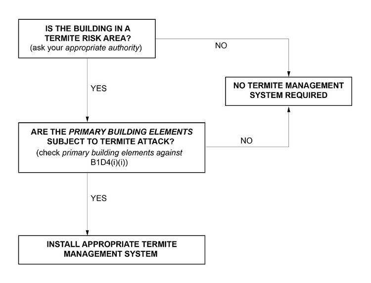
Table B1D4 describes acceptable glazing permitted in the construction of lift shafts. The inherent strengthened qualities of these glazing types is considered for the purposes of B1D4(m)(iii) 'non brittle'. 

(1) Structural software used in computer aided design of a building or structure, that uses design criteria based on the Deemed-to-Satisfy Provisions of the BCA, including its referenced documents, for the design of steel or timber trussed roof and floor systems and framed building systems, must comply with the ABCB Protocol for Structural Software.

(2) Structural software referred to in (1) can only be used for buildings within the following geometric limits:

  1. The distance from ground level to the underside of eaves must not exceed 6 m.
  2. The distance from ground level to the highest point of the roof, neglecting chimneys, must not exceed 8.5 m.
  3. The building width including roofed verandahs, excluding eaves, must not exceed 16 m.
  4. The building length must not exceed five times the building width.
  5. The roof pitch must not exceed 35 degrees.

(3) The requirements of (1) do not apply to design software for individual frame members such as electronic tables similar to those provided in—

  1. AS 1684; or
  2. NASH Standard Residential and Low-Rise Steel Framing Part 2.


B1D5 does not apply where a software package simply eliminates manual calculations and the process of the package requires identical methodology as that undertaken manually, e.g. AS 1684 span tables and bracing calculations.

NCC Title
Construction of buildings in flood hazard areas
NCC State
SA
NCC Variation Type
Deletion
NCC SPTC Current
Construction of buildings in flood hazard areas
NCC Blurbs

(1) A Class 2 or 3 building, Class 9a health-care building, Class 9c building or Class 4 part of a building, in a flood hazard area must comply with the ABCB Standard for Construction of Buildings in Flood Hazard Areas.

(2) The definitions of flood hazard area and freeboard in the ABCB Standard for Construction of Buildings in Flood Hazard Areas are replaced with those in VIC Schedule 1.

(3) The definition of defined flood level in the ABCB Standard for Construction of Buildings in Flood Hazard Areas is replaced with that in VIC Schedule 1.

NCC Title
Construction of buildings in flood hazard areas
NCC State
VIC
NCC Variation Type
Replacement
NCC SPTC Current
Construction of buildings in flood hazard areas
NCC Title
Construction of buildings in flood hazard areas
NCC State
QLD
NCC Variation Type
Deletion
NCC SPTC Current
Construction of buildings in flood hazard areas
NCC Notice
Building work in designated flood hazard areas is regulated by the Building Act 1975, and the Queensland Development Code 3.5 - Construction of buildings in flood hazard areas.

(1) A building in a flood hazard area must comply with the ABCB Standard for Construction of Buildings in Flood Hazard Areas.

(2) The requirements of (1) only apply to a Class 2 or 3 building, Class 9a health-care building, Class 9c building or a Class 4 part of a building.


B1D6 requires the specified buildings in a flood hazard area to comply with the ABCB Standard for Construction of Buildings in Flood Hazard Areas. Under the definition of ”flood hazard area” the appropriate authority (usually the relevant local government) is responsible for determining the extent of land lower than the flood hazard level. The flood hazard level is used to determine the minimum height of floors of a building above the flood waters. The flood hazard area may be mapped in a local government planning instrument.

The prescriptive provisions of the ABCB Standard only apply to flood hazard areas where the maximum flow velocity is not greater than 1.5 m/s. Where the appropriate authority is unable to determine whether the maximum flow velocity is not greater than 1.5 m/s, the prescriptive provisions only apply to inactive flow or backwater areas, i.e. not directly adjacent to a watercourse or floodway.
Where the maximum flow velocity is greater than 1.5 m/s it would be necessary to formulate a Performance Solution which complies with the relevant Performance Requirements. This would involve the application of engineering practice to determine appropriate design solutions.