F3V1 Weatherproofing
F3V1 is a means to verify whether or not a proposed external wall achieves the requirements of F3P1, i.e. whether the wall prevents the penetration of water that could cause:
- unhealthy or dangerous conditions or loss of amenity for occupants; and
- undue dampness or deterioration of building elements.
F3V1 is not a mandatory component of the NCC; however, it is one form of assessment method that can be used to demonstrate compliance with the Performance Requirements.
Other assessment methods in the NCC include:
- evidence to support that the use of a material, form of construction or design meets the Performance Requirement or a Deemed-to-Satisfy Provision;
- comparison with a Deemed-to-Satisfy Provision where applicable; or
- expert judgement, which means the judgement of an expert who has the qualifications and experience to determine whether a solution complies with the Performance Requirements.
The Verification Method must be applied in the following order:
- confirm the limitations of F3V1(1)(b) are met;
- develop a test specimen including representative samples of openings and the like (F3V1(3));
- test the specimen in accordance with the relevant test procedure (F3V1(4) or (5));
- assess the specimen against the compliance criteria (F3V1(6)); and
- record the test results (F3V1(7)).
This process is shown in Figure F3V1a.
Figure F3V1a: Process for applying F3V1
Risk factors—Table F3V1a
The risk score is determined by a number of factors including:
- wind region;
- number of storeys;
- type of roof/wall junctions;
- eave widths;
- complexity of the building envelope; and
- types of decks, porches and balconies.
The following are examples of typical roof/wall junctions and their associated exposureor protection categories:
- a hip and gable roof with eaves is considered to have fully protected roof-to-wall junctions;
- a hip and gable roof with no eaves is considered to have partially exposed roof-to-wall junctions;
- parapets, enclosed barriers or eaves at greater than 90° to vertical with soffit lining are considered fully exposed roof- to-wall junctions; and
- lower ends of aprons, chimneys, dormer windows and the like are considered roof elements finishing within the boundaries formed by the external walls.
Building envelope complexity is determined by the shape and the amount of cladding used. F3V1 includes both simple and complex shaped buildings:
- A simple shaped building includes rectangular, L or T shaped buildings.
- A complex shaped building includes a building with angular or curved shapes such as a Y shaped building.
Test specimen—F3V1(3)
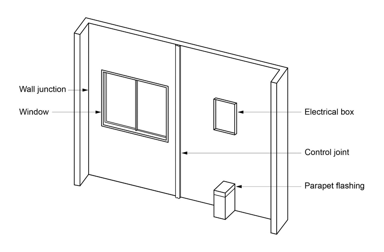
Representative samples of openings and joints must be includedto test the whole cladding system. This includes samples of:
- vertical and horizontal control joints;
- wall junctions;
- windows or doors;
- electrical boxes;
- balcony drainage(i.e. to prevent water pooling against the external wall) and parapet flashings; and
- footer and header termination systems (i.e. a header termination system is where a cladding finishes at the top of a window).
A test specimenis illustrated in Figure F3V1b
Figure F3V1b: Illustration of a test specimen
Where a cavity wall is tested, a transparent material must be used in lieu of a portion of the internal wall lining. The transparent material will be used during the testing to observe any water penetration. To ensure an unobstructed view of the external wall occurs, other building components such as building membranes must be removed for the extent of the transparent opening within the internal wall lining. It should be noted that for the purposes of F3P1 building membranes are not a requirement. However, a membrane can be used to achieve compliance with F3V1.
The transparent material must be installed to maintain similar air tightness as the intended internal wall lining. To simulate the effects of power points, light switches and other similar openings which may cause air leakage, a 15 mm diameter hole must be placed in the internal wall lining below the window.
Test procedure—F3V1(4) and (5)
The test procedure requirements vary in relation to two sub-clauses. F3V1(4) specifies the test procedure for a direct fix cladding wall or a unique wall. F3V1(5) specifies the requirements for cavity wall construction. The difference betweenthe two sub-clauses is F3V1(5) has an additional water management test. This is due to cavity wall construction being designed to allow water to pass through the primary weather-defence (e.g. the skin of masonry on a masonry veneer wall), with the function of the cavity allowing for the removal of any water.
Direct fix cladding wall and unique wall—F3V1(4)
The test procedure for F3V1(4) contains three steps:
- Apply a preconditioning loading to the external face of the wall, by placing 100% positive and 100% negative (suction) serviceability wind pressure to the external wall. The serviceability wind pressure will be determined by the location in which the wall is going to be installed. However, due to the limitations of the Verification Method, the ultimate state wind pressure can be a maximum of 2.5 kPa. For a vented cavity wall, the end sections of the cavity must be sealed and the material serving as the air seal must be able to withstand the same applied loading as the wall being tested.
- Conduct a static pressure test at 30% of the serviceability wind pressure or 300 Pa, whichever is higher. F3V1(4)(b) refers to clause 8.5.2 ofAS/NZS 4284 for the requirements of this test.
Apply cyclic pressure and test the water penetration in accordance with clause 8.6.2of AS/NZS 4284, tested over the three stages specified in Table F3V1b.
Cavity walls—F3V1(5)
The test procedure for F3V1(5) contains four steps:
- The first two steps are identical to F3V1(4) in respect to the preconditioning loading test and the static pressure test.
- The third test, the cyclic pressure test, is slightly different to the cyclic pressure test in F3V1(4). The test is still required to be in accordance with clause 8.6.2 of AS/NZS 4284. However, instead of testing three stages of Table F3V1b, F3V1(5)(c) only requires one test, using serviceability wind pressures of stage three of Table F3V1a. Only one cyclic pressure test is required as the water management test in F3V1(5)(d) requires additional tests; one additional cyclic test and two additional static pressure tests.
F3V1(5)(d) contains the additional testing requirements for a cavity wall. This test represents the failure of the primary weather defence or sealing. The primary weather defence includes the wall material, any flashings and sealing of joints and openings.
Compliance—F3V1(6)
Similar to the test procedure, the compliance requirements are separated into two parts and are subject to the type of wall being tested.
F3V1(6)(a) specifies the compliance requirements for a direct fix cladding wall and a unique wall. Compliance for the testing of these types of walls is met by no presence of water to the inside surface of the facade. This includes the surface of the external wall which is fixed to the internal wall, or for a single skin wall, the internal wall.
The compliance requirements for a cavity wall in F3V1(6)(b) are different to the requirements for a direct fix cladding wall or unique wall. This is due to the purpose and nature of a cavity wall. Water which passes through the primary weather- defence will gradually be removed from the cavity either through weep holes or evaporation. F3V1(6)(b) therefore allows water to enter the cavity provided water is not present on the removed surface of the cavity. However, there are some exemptions to this, as the water may transfer to the removed surface through an isolated blemish due to the introduced defects. Also, water can contact cavity surfaces such as battens. However, it must be demonstrated that the water will be able to be removed from these surfaces.
The removed surface of the cavity will generally be the outer surface of the internal wall, for example,where the building membrane would be attached to a stud frame.
The purpose of the test report in F3V1(7) is to record the details and the outcomes of the test. This is common for any test procedure.